Key Takeaways
5-axis = X/Y/Z plus two rotary axes; the A+C diagram shows A = tilt and C = rotate to reach angled and multi-face features.
“5-axis” can mean 3-axis, 3+2 (indexed), or simultaneous 5-axis. The key difference is whether rotary axes lock before cutting or move during the cut.
Machine layouts vary (trunnion/table–table, head–table, head–head), which changes real limits like clearance, reach, and part size.
To read a diagram for a real part, think approach direction, setup reduction, and collision/clearance risks (tool length, holder, trunnion limits).
5-axis is most justified by geometry like compound angles, undercuts, freeform surfaces, deep angled pockets, and tight cross-face relationships—and quoting goes fastest with clear CTQs + inspection/doc requirements upfront.
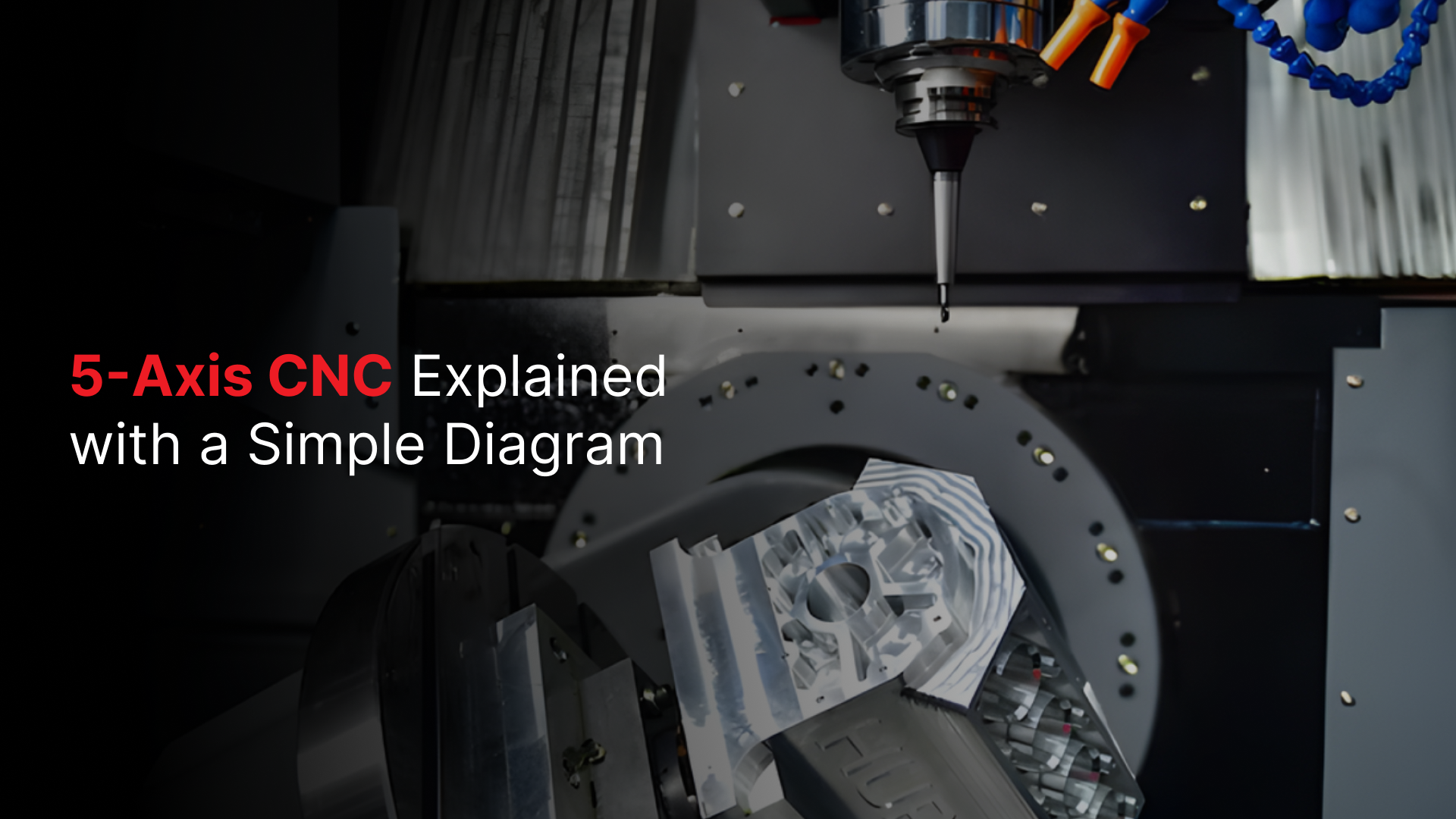
If you searched for a 5-axis CNC machine diagram, you’re probably trying to answer one practical question: what moves, and what do the axes actually mean? The fastest way to understand 5-axis machining is to anchor everything to a simple picture, then map each axis label (X, Y, Z, A, C) to real motion on the machine.
Below is a conceptual A+C 5-axis setup. It’s intentionally simplified so you can read it quickly and apply it to parts, drawings, and quotes.
5-Axis CNC Machine Diagram
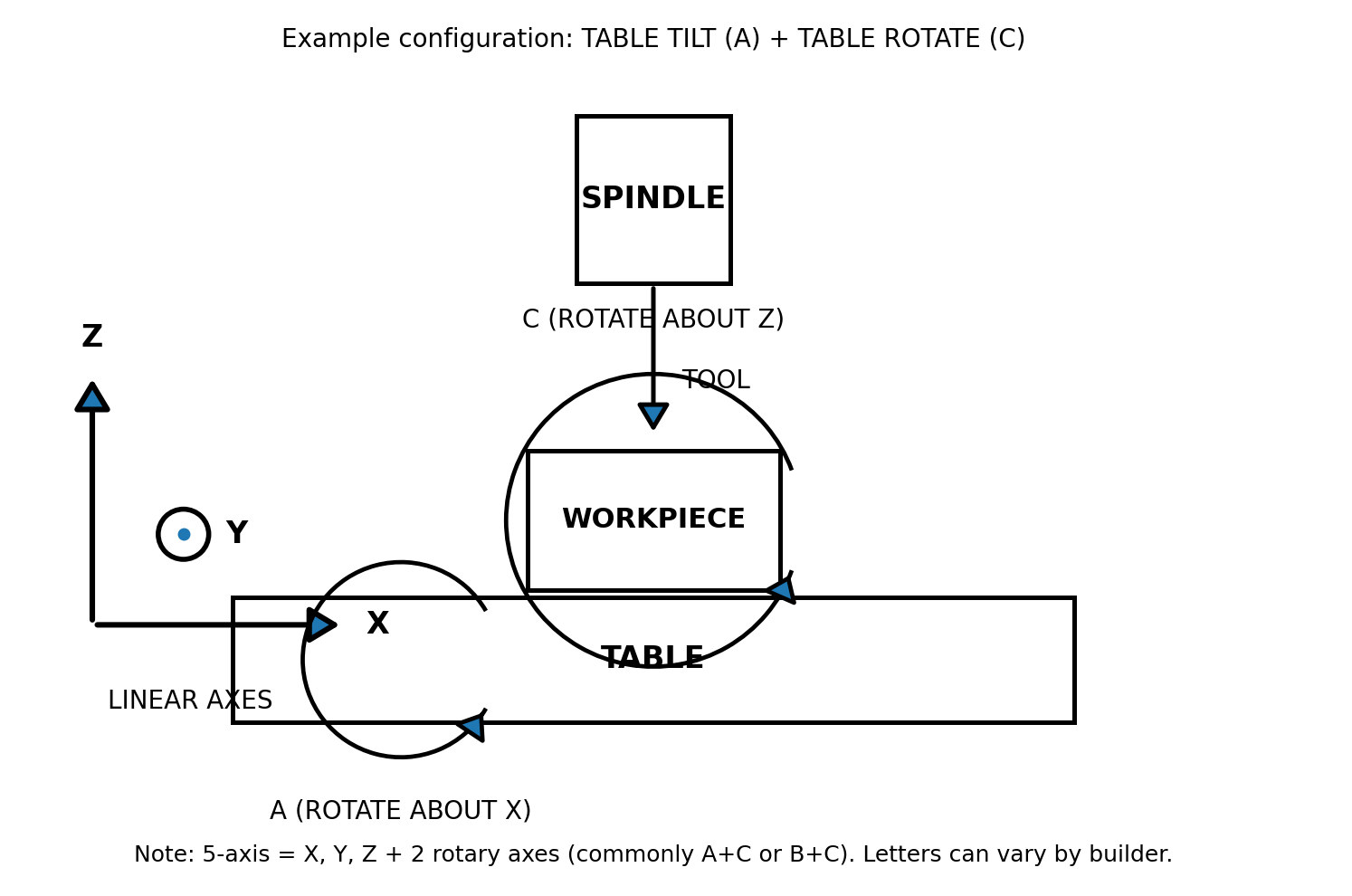
A+C 5-axis example: three linear axes (X/Y/Z) plus two rotary axes, A tilt about X and C rotation about Z.
What you’re looking at:
This diagram shows a CNC milling setup: the spindle holds the cutting tool, and the table holds the workpiece.
A “5-axis” system combines:
3 linear movements (X, Y, Z) for positioning
2 rotary movements (A + C) for orienting the part/tool
(Next section breaks down what each axis does on real parts.)
Why we’re using A+C in this diagram:
Many 5-axis machines add two rotary axes, but the pair isn’t always the same. Most commonly, you’ll see A+C or B+C, depending on the machine design. If you’re trying to learn from a diagram, showing A+C keeps things simple.
When a diagram shows A, B, and C all at once, it can easily confuse you into thinking the machine has more than five axes (or that all three rotations happen together).
This A+C version provides a clean mental model first, making it easy to translate to other 5-axis setups later.
Also note that axis letters can vary by machine builder, but the concept of linear axes plus two rotations remains the same.
What the 5 Axes Mean
The easiest way to make the axis letters “stick” is to stop thinking of them as abstract labels and start thinking in two jobs:
X / Y / Z = positioning (getting the cutter to the right place)
A / C = orientation (aiming the part so the cutter can reach the feature)
In the A+C diagram you’re using, here’s what each axis does for you when you’re trying to machine a real part.
X axis: left–right positioning across the table
Use X to move the cutting location side-to-side across the work envelope. Practically, X is what you rely on for:
locating features along a length (slots, pockets, bolt patterns)
stepping between machining positions without re-clamping
What to look for in drawings: long patterns or features that repeat across a face often map to X moves (along with Y).
Y axis: front–back positioning across the table
Y moves the cutting location front-to-back. Think of Y as the axis that lets you “scan” across a face in the other horizontal direction. You’ll feel Y the most when:
facing a surface
pocketing and profiling across a plane
interpolating holes with circular toolpaths
Quick mental check: if you’re machining a flat face, you’re almost always using X + Y together.
Z axis: depth and “tool into the part.”
Z controls the depth of cut, how the tool approaches, engages, and retracts from the workpiece. This is the axis most tied to:
stepdowns in a pocket
drilling depth
controlling approach/retract clearance (avoiding clamps/fixtures)
Why Z matters on 5-axis: even when you rotate the part (A/C), you still need clean Z strategies for safe approaches and consistent surface finish.
A axis (rotate about X): the “tilt” that exposes angled faces
A is the tilt axis in your diagram rotation around X. This is the motion that lets you bring an angled face or feature into a machinable orientation without weird tool angles or multiple setups.
A is especially useful when your part has:
compound angles that can’t be reached straight-on
features on “side walls” or sloped surfaces
critical relationships between features on different faces (because you can machine them with fewer re-clamps)
What A often replaces: physical angle plates, awkward fixtures, or repeated re-indicating between setups.
C axis (rotate about Z): the “spin” that changes which side is facing the tool
C is the rotation around Z in your diagram; think of it as spinning the table/part around a vertical axis. C is great for:
Indexing around the part (e.g., 4 holes at 90° increments, or repeating features around a center)
Keeping tool access consistent while you rotate to the next feature
Reducing setup changes for parts with features distributed around a perimeter
When C shines: circular patterns, clocking features around a hub, and machining multiple sides while holding one datum.
The practical takeaway: what 5 axes really buy you
On a 3-axis mill, you mostly win by moving to the right position. On an A+C 5-axis setup, you win by controlling both:
Where the tool cuts (X/Y/Z)
What angle the work is presented to the tool (A/C)
That combination is why 5-axis machining is often less about “fancy motion” and more about reach, fewer setups, and better access to complex geometry.
Next, you’ll see the key difference: are you just positioning the part with A+C and then cutting like 3-axis (3+2), or are you moving all five axes during the cut (simultaneous 5-axis)?
3-Axis vs 3+2 vs True Simultaneous 5-Axis
Even though people say “5-axis” casually, it usually means one of three machining modes.
3-axis keeps the tool orientation fixed and only moves in X/Y/Z.
3+2 (positional 5-axis) uses the rotary axes (like A and C in your diagram) to index the part to a set angle, then machines that feature standard 3-axis motion.
True simultaneous 5-axis moves X/Y/Z and the rotary axes at the same time, continuously changing tool orientation during the cut, which is what enables smooth machining over complex 3D surfaces and compound angles without leaving transitions from indexing.
Quick comparison
Mode | How it works | Typical applications |
|---|---|---|
3-axis | Tool orientation stays fixed; only X/Y/Z move | Flats, pockets, simple prismatic parts |
3+2 (indexed 5-axis) | A/C rotate to an angle, then lock; cut like 3-axis | Angled planes, multi-face parts, 5-sided machining in one clamp |
Simultaneous 5-axis | A/C move while cutting along with X/Y/Z | Complex 3D surfaces, compound angles, continuous finish |
Common pitfalls
3-axis pitfalls
More setups to reach multiple faces → more chances to introduce alignment error
Long tool stick-out for reach → higher deflection, chatter, and inconsistent finish
Workholding becomes the limiting factor sooner (you “run out of access”)
3+2 (indexed) pitfalls
It’s easy to underestimate clearance (holder, spindle nose, trunnion/table limits)
Wrong index angle or datum strategy → features clocked or located incorrectly.
You can still create “setup-like” errors if you’re indexing from inconsistent references.
Simultaneous 5-axis pitfalls
Collision risk goes up fast (tool/holder/table/part), especially with tight clearances.
Results depend heavily on toolpath strategy + post-processor + machine limits.
Poor settings can show up as faceting/scallops or an inconsistent finish on surfaces.
If you can reach everything straight on, the 3-axis is the simplest.
If you need access to angled faces but the cut itself can be done at a fixed orientation, 3+2 is often the sweet spot; this is where your A+C diagram applies most directly.
Go with simultaneous 5-axis when the geometry demands continuous orientation (complex surfaces or compound angles where indexing would leave visible transitions or require too many repositioned cuts).
Common 5-Axis Machine Configurations
5-axis machines don’t all share the same physical layout. The main difference is where the rotary motion is built in: on the table, on the head, or split between both. That placement changes what’s easiest to machine, especially around clearance, reach, and part size.
Table–Table (Trunnion)
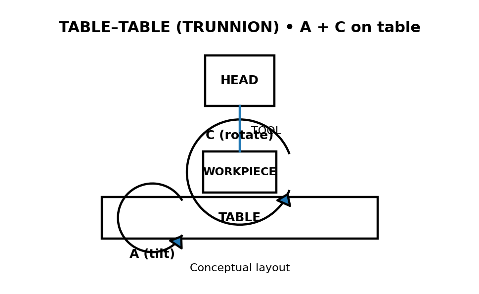
Table–table (trunnion): both rotary axes are on the table/workholding side (often A + C).
What rotates / where the rotary axes sit
In a table–table setup, both rotary axes live on the table side. This is the configuration that looks most like your A+C hero diagram, because the part is being tilted (A) and rotated (C) while the spindle stays relatively straightforward.
Typical strengths
Great for multi-face access in one clamp (you can tilt and rotate the part into position)
Often very effective for 3+2 (indexed) work, where you lock an angle and then cut like a 3-axis
Strong option for small-to-medium parts that fit comfortably within the rotary envelope
Typical limits
Clearance is the common constraint (tool holder + table + part can collide at extreme tilts)
Part size is limited by the rotary table’s swing and workholding space
Head–Table (Swivel Head + Rotary Table)
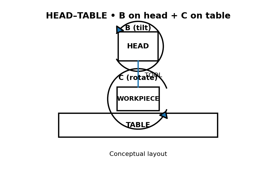
Head–table: one rotary axis is in the head (often B tilt), and one is on the table (often C rotate).
What rotates / where the rotary axes sit
In a head–table setup, one rotary axis is built into the spindle head (tilt), and the other rotary axis is on the table (rotation). In simple terms, the machine can aim the tool and clock the part.
Typical strengths
More reach and flexibility around fixtures and taller parts (because the head can do much of the orientation)
Good “generalist” layout for a wide variety of part geometries
Often reduces the need for awkward workholding compared to purely table-based rotation
Typical limits
More head motion means you must be more careful about collision checking and tool length.
Results can depend heavily on a well-tuned post-processor + machine kinematics.
Head–Head
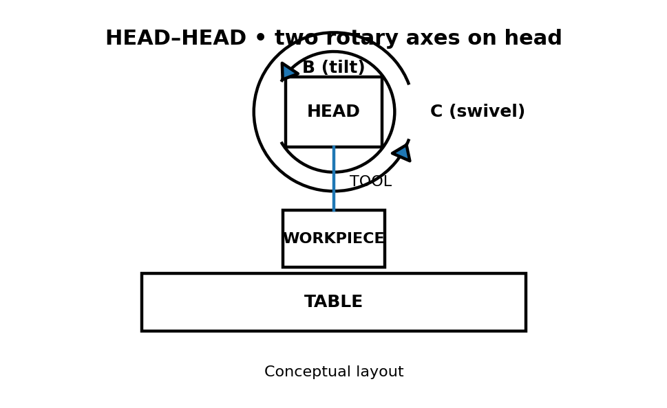
Head–head: both rotary axes are in the spindle head; the table stays comparatively simple.
What rotates / where the rotary axes sit
In a head–head setup, both rotary axes are in the spindle head. Instead of moving the part with a complex rotary table, the machine does most of the orientation up top.
Typical strengths
A common advantage for large or heavy parts, that you’re not asking a rotary table to swing a big load
Workholding can stay more robust and straightforward while still getting multi-angle access.
Helpful when the part size or weight would be awkward on a trunnion-style setup
Typical limits
Moving more mass in the head can make rigidity and cutting strategy more important.
You may need to plan around certain orientation “sweet spots” to avoid awkward angles.
No matter the layout, the practical question is the same: does the machine get access by moving the part, moving the head, or a mix of both, and what does that imply for clearance and part size?
How to Read a 5-Axis Diagram for a Real Part
The diagram is useful only if you can look at a part and quickly answer two questions: (1) what direction does the tool need to approach from? And (2), can you get that approach in one setup without hitting anything? The A+C model helps you think through both without getting buried in machine-specific details.
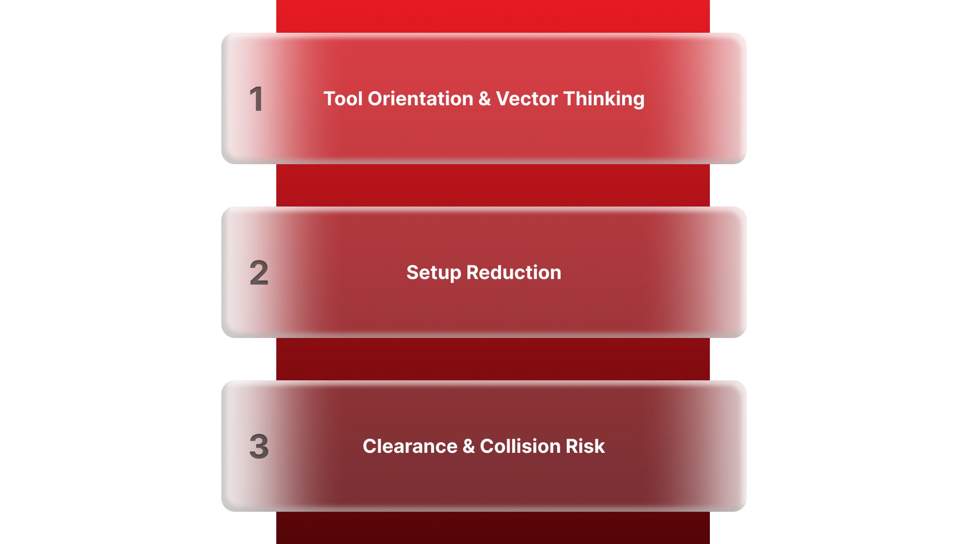
Tool orientation and “vector thinking.”
When you see a feature on a drawing, don’t start by thinking “A axis” or “C axis.” Start by thinking feature direction.
Every face or feature has a “most natural” approach direction (imagine an arrow pointing straight out of the surface).
Your goal is to orient the part so the tool can approach along that direction cleanly.
How the A+C diagram maps to that:
Use A (tilt) to change the angle of the part so the feature is no longer “slanted” relative to the tool.
Use C (rotate) to “clock” the part so the feature is facing the right side, then repeat around the part if needed.
Quick mental workflow
If a feature is on a flat top face, you likely don’t need tilt.
If a feature is on an angled face, you’ll typically tilt with A until that face is presented cleanly.
If the same feature repeats around the part (bolt circle / multiple sides), you’ll often rotate with C to hit the next one.
Setup reduction (why 5-axis often means fewer fixtures)
The biggest practical win is not “fancier motion,” it’s doing more work in one clamp so you don’t stack errors across multiple setups.
Think “5-sided machining” like this:
In a 3-axis world, you machine one face, then you physically flip/reclamp to reach another face.
With the A+C model, you can often keep the part clamped once and use A to present a new face and C to rotate to the next orientation.
What does this change for you?
You can keep the same datum references longer (less re-indicating).
Features on different faces can hold tighter relationships because they’re made under one consistent setup.
You spend less time designing “creative” fixtures just to reach a surface.
A quick decision cue
If you’re looking at a part and thinking “this needs 3–4 flips,” that’s a strong sign the A+C approach can cut setups down sometimes to one.
Clearance and collision risk (what the diagram doesn’t show)
The diagram makes axis motion look simple, but real machines have limits, and most 5-axis problems are clearance problems, not “axis definition” problems.
Before you assume a tilt/rotation will work, sanity-check these:
Tool length vs stiffness: Longer tools reach deeper features, but they’re easier to deflect and can chatter.
Holder clearance: The holder often hits first, not the tool. Tight pockets + big tilt angles can be a bad combo.
Trunnion/table limits: Extreme A tilts can bring the part closer to the spindle/holder envelope than you expect.
Workholding footprint: A fixture that’s “fine” in 3-axis can become the collision point once you start tilting/rotating.
Safe approach path: It’s not just “can you cut it?”, it’s “can you approach and retract safely at that angle?”
Note: If a feature requires a big tilt and sits deep in a pocket, assume you’ll need extra clearance planning (tool, holder, and fixture), even if the axis motion itself is possible.
When 5-Axis Is the Right Choice
You pick 5-axis because it’s the cleanest way to get access + accuracy without turning your job into a fixture-and-reclamp project.
Geometry That Justifies 5-Axis
Compound angles where a single fixed tool direction can’t hit the feature cleanly
Undercuts/back-side reach that would force awkward tooling or multiple reorientations
Sculpted / freeform surfaces where the tool angle needs to change to maintain contact and finish
Deep pockets with angled walls (especially when holder clearance becomes the real limiter)
Multi-face parts where important features live on several sides and need to stay tightly related
Tight positional tolerances across faces (features that must “line up” when measured from a common datum set)
Features close to clamps/fixtures, where changing orientation is the safest way to create access.
Parts that would otherwise need 3–4+ flips to complete (a big signal you’re fighting the setup)
When 3-axis or 3+2 is enough
The geometry is mostly prismatic and reachable from one or two straightforward directions.
Angled features exist, but they can be handled by indexing once or twice (3+2) without needing continuous motion.
Surface finish requirements are normal and don’t depend on a continuously changing tool angle.
You’re not trying to hold critical relationships between features on multiple sides in a single datum scheme.
The part is large/simple enough that extra axis motion adds complexity without a real payoff.
Simple rule: If you can machine it cleanly with a couple stable setups, don’t force 5-axis. If the part’s geometry is forcing you into too many flips, long tools, or sketchy access, 5-axis stops being “extra” and starts being the most straightforward option.
Quick Checklist Before You Quote a 5-Axis Part
Use this as a “send-this-with-your-RFQ” checklist. If you include these upfront, you reduce back-and-forth and lower the chance of surprises in lead time, inspection, or cost.
CAD + drawing
Native CAD or neutral file (STEP/IGES) + a PDF drawing if available
Call out any “model is master” vs “drawing is master” expectation
Material + any special processes
Exact material spec/grade (not just “aluminum”)
Heat treat condition and any post-process needs (coatings, passivation, anodizing, etc.), if applicable
Critical dimensions + GD&T
Highlight the true critical-to-function features (don’t make the shop guess)
Include GD&T callouts, datums, and tolerance stack assumptions if relationships matter across faces.
Surface finish requirements
Surface finish values where they matter (and which faces)
Cosmetic requirements (tool marks allowed/not allowed) if appearance is important
Inspection + documentation expectations
First Article / FAI requirement (yes/no)
CMM report required (yes/no), and what features must be reported
Traceability needs (material certs, lot control, certificates of conformance)
Quantity + timing
Prototype vs production intent (one-off, pilot run, full run)
Annual volume estimate of recurring
Target due date and whether partial shipments are acceptable
With those details included, a 5-axis quote becomes faster, cleaner, and far less likely to change midstream. The next question is simply: who can machine it consistently—and deliver the inspection and documentation your program requires? That’s where Criterion Precision fits.
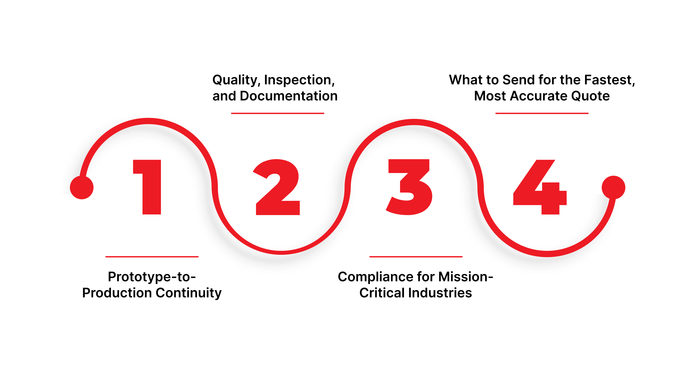
5-Axis Machining at Criterion Precision
Criterion uses 5-axis machining when the job needs repeatable, low-risk access and the output has to fit a mission-critical supply chain. Typical fit looks like:
Programs where cross-face relationships are critical, and you want to avoid chasing alignment across re-clamps
Parts that need clearance-aware access without sacrificing rigidity or inspection strategy
Builds that require inspection-ready deliverables (defined CTQs, documented verification, traceability expectations)
Prototype-to-production work where you want the same machining approach and quality framework to carry through scaling
Prototype-to-production continuity
Criterion supports programs that start as prototypes, move into low-volume builds, and scale into repeat production without changing the quality framework midstream, useful when you want continuity through design validation, iteration, and steady-state manufacturing.
Quality, inspection, and documentation
For regulated parts, the deliverable isn’t just the component, it’s the evidence behind it. Criterion is built around shipping parts that are:
Fully inspected (including dimensional verification where required)
Delivered with inspection reports/certificates of conformity aligned to regulated supply chains
Supported by traceability documentation and controlled records for audits and supplier qualification workflows
Compliance for mission-critical industries
Criterion is an audit-ready supplier for high-reliability programs, with compliance and registrations that support regulated buying requirements:
ISO 13485
ISO 9001:2015
FDA registered
ITAR registered
DFARS compliant
WBENC-certified woman-owned business
What to send for the fastest, most accurate quote
To move quickly and avoid quote changes later, Criterion-specific “speed levers” are:
Mark CTQ features clearly (critical-to-quality dimensions, datums, and any cross-face relationships you care about most)
State inspection output expectations upfront (e.g., which characteristics must be reported, FAI expectations if applicable, traceability requirements)
Call out compliance constraints early (ITAR/export-controlled handling, documentation retention needs, customer-specific quality notes)
Include revision control context (current rev, what changed since last rev, and what must not change)
If you want a fast read on manufacturability before committing, send your drawing + CTQs, and we’ll confirm whether 3+2 or true 5-axis is the right approach, then quote with the inspection/documentation plan upfront. Request a Quote.
Conclusion
A 5-axis CNC diagram is a shortcut to better decisions: you can look at a part and quickly tell whether the job is simple positioning, indexed machining, or true multi-axis work.
Once you start reading drawings that way, quoting and planning get more predictable, because you’re thinking about access and risk upfront instead of discovering them during setup and programming.
FAQs
What are the 5 axes in CNC?
In a typical 5-axis milling setup, you have three linear axes (X, Y, Z) plus two rotary axes. The rotary axes are usually labeled from A, B, and C, but a given machine will only use two of them at a time (for example, A + C, like the diagram in this article).
What’s the difference between 3-axis and 5-axis?
A 3-axis machine moves in X/Y/Z with a fixed tool orientation. A 5-axis machine adds rotary motion so the part (or tool) can be oriented to reach angled faces and multiple sides more efficiently.
What does “3+2” mean?
3+2 (indexed 5-axis) means the machine uses the rotary axes to tilt/rotate to a set angle, then locks that orientation and cuts using standard 3-axis motion. It’s often the simplest way to machine angled planes and multiple faces without full simultaneous motion.
Do all 5-axis machines use A/B/C the same way?
The convention is A rotates about X, B about Y, and C about Z, but how builders label axes can vary. The key idea is consistent: you still have three linear axes plus two rotations, regardless of the exact lettering.
What are trunnion vs swivel-head machines?
A trunnion (table–table) setup puts rotary motion on the table/workholding side, so the part is tilted and rotated. A swivel-head (head–table) setup puts at least one rotary axis in the spindle head, changing the tool orientation while the table may provide rotation.