
Introduction
An engineer submits a drawing with coordinate dimensions for a critical medical device component. The parts come back from the machine shop perfectly matching the specified measurements—yet they don't fit together during assembly. The culprit? Missing or inadequate Geometric Dimensioning and Tolerancing (GD&T) specifications.
This scenario plays out in manufacturing facilities daily, costing companies thousands in scrap, rework, and delayed deliveries. The numbers back it up: proper GD&T implementation reduces scrap rates from 4.2% to 1.1% and cuts rework instances by 62%, making it one of the most impactful tools for precision manufacturing.
GD&T is a symbolic language that communicates design intent and acceptable part variation. It goes beyond specifying measurements.
Unlike coordinate tolerancing, GD&T describes what matters functionally: how surfaces relate to each other, which features control assembly, and where tolerances can be relaxed without compromising performance.
This guide covers the fundamentals — datums, feature control frames, the five symbol categories, and how to work effectively with machine shops on GD&T specifications for precision machined components.
What is GD&T and Why Does It Matter for Precision Parts?
The Evolution from Traditional Tolerancing
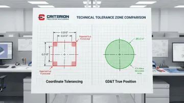
Traditional coordinate tolerancing uses simple plus/minus dimensions to define part geometry. A hole specified as 0.500" ±0.005" creates a square tolerance zone measuring 0.010" on each side. But holes are round, and fasteners move in circular patterns during assembly — coordinate zones don't reflect that reality.
GD&T's circular tolerance zones provide 57% more allowable tolerance area than equivalent square coordinate zones. This means parts that would be rejected under coordinate tolerancing actually function perfectly in their assemblies—reducing false rejections without compromising quality.
Stanley Parker developed GD&T during World War II at the Royal Torpedo Factory in Scotland, after observing functional parts rejected for falling outside square X-Y tolerance zones despite fitting their assemblies. His 1940 publication introduced "True Position" and cylindrical tolerance zones — a shift that changed how manufacturing requirements are written and read.
Today, two primary standards govern GD&T globally:
- ASME Y14.5-2018: The U.S. standard used extensively in aerospace and defense
- ISO 1101:2017: The international standard used globally
These standards differ in one key area: ASME defaults to the "Envelope Principle" (Rule #1), where size limits also control form. ISO uses the "Independency Principle," treating size and form as independent unless otherwise specified.
Why GD&T is Essential for Precision Machining
GD&T describes design intent rather than just geometry. It tells machinists what matters functionally, not just what the shape should be. A shaft that must rotate freely in a bearing needs different controls than one transferring torque, and GD&T captures that difference explicitly.
Used well, GD&T actively reduces cost by specifying the loosest tolerances that still ensure function:
- Tightening tolerances from ±0.05mm to ±0.01mm can multiply production costs 2–24x due to added fixturing, environmental controls, and inspection demands
- Material condition modifiers enable bonus tolerance, letting functional parts pass inspection that would otherwise be scrapped
- Appropriate tolerancing keeps costs in check without sacrificing fit or performance
For precision machining shops serving medical device, aerospace, defense, and photonics industries, GD&T isn't optional — it's foundational. These sectors demand parts that are right the first time, with tolerances as tight as ±0.0002". ISO 13485 and ISO 9001 quality systems depend on clear GD&T callouts for traceability and compliance throughout the supply chain.
Benefits of Implementing GD&T
GD&T functions as a universal communication standard across the full manufacturing chain:
- Creates consistent interpretation between design engineers, machinists, and quality inspectors
- Supports global manufacturing through symbols that transcend language barriers
- Eliminates ambiguity across departments and suppliers
That clarity translates directly into measurable efficiency gains on the shop floor and in the inspection lab.
On the quality and efficiency side, the numbers are concrete:
- Enables statistical process control (SPC) with clear, measurable criteria
- Reduces inspection time and costs by 35% through automated CMM routines
- Improves assembly success rates by controlling the features that matter for fit and function
- Reduces machining preparation costs by 35% and inspection costs by 50% when paired with Model-Based Definition
Understanding Datums and Datum Reference Frames
What are Datums?
A datum is a theoretically exact point, line, or plane used as a reference for measurement. In practice, it functions like the origin point in CAD: the fixed reference from which all other features are measured.
Key distinctions:
- Datum: The theoretical reference (perfect plane, axis, or point)
- Datum Feature: The actual physical feature on the part (machined surface, cylindrical surface, or hole) identified by a datum feature symbol
A flat machined surface becomes the datum feature. The theoretically perfect plane derived from that surface—established by the three highest points in contact with a surface plate—becomes the datum itself.
The Datum Reference Frame (DRF)
The Datum Reference Frame is a 3D coordinate system established by datums, providing the reference for all measurements. It constrains the six degrees of freedom (three translational, three rotational) necessary to fully locate a part in space.
The 3-2-1 Rule:
This fundamental principle defines how datums constrain degrees of freedom:
Primary datum (3 points): Contacts the part at minimum three points, constraining 3 degrees of freedom (two rotations and one translation). Typically a large flat surface resting on a surface plate.
Secondary datum (2 points): Contacts the part at minimum two points, constraining 2 degrees of freedom (one rotation and one translation). Often an edge or cylindrical surface touching an angle block.
Tertiary datum (1 point): Contacts the part at minimum one point, constraining the final 1 degree of freedom (one translation). Prevents the part from sliding along the remaining axis.
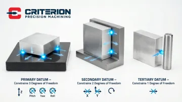
Picture a rectangular block placed on a surface plate (primary datum), pushed against an angle block (secondary datum), and touching a pin (tertiary datum). The part is now fully constrained and repeatable for measurement.
Selecting Appropriate Datums
Functional precedence principle:
Choose datums based on how the part mounts and functions in final assembly, not manufacturing convenience. If a part bolts to a housing using a flat surface and two locating pins, those features should be your datums—in that order of importance.
Selection criteria:
- Large, flat surfaces or well-defined cylindrical features that won't rock or deform under measurement
- Consistent contact points that fixturing and inspection equipment can reliably reproduce
- Features physically accessible to CMM probes and other inspection tools
For precision machined parts, the first machined surface often becomes the primary datum for subsequent operations, ensuring all features relate properly to each other throughout the manufacturing process.
Datum Feature Modifiers
Once datums are established, material condition modifiers determine how tightly geometric tolerances apply relative to actual feature size. Choosing the right modifier directly affects how much manufacturing variation is permissible.
In photonics and optics components — where bore concentricity directly controls optical path alignment — RFS is the standard call. Any bonus tolerance introduced by MMC creates variability the application can't absorb. Criterion Precision Machining regularly machines these components to tolerances of ±.0002", where modifier selection is as consequential as the tolerance value itself.
Feature Control Frames Explained
Anatomy of a Feature Control Frame
The Feature Control Frame (FCF) is a rectangular box divided into compartments, read from left to right:
Compartment structure:
- Geometric characteristic symbol (leftmost): Defines the type of control (position, flatness, perpendicularity, etc.)
- Tolerance value: Specifies total allowable variation, preceded by diameter symbol (Ø) for cylindrical zones
- Datum references: Lists primary, secondary, and tertiary datums in order of precedence
Material condition modifiers (MMC/LMC) appear as circled letters next to tolerance values or datum references when applicable.
Reading and Interpreting Feature Control Frames
Step-by-step interpretation process:
- Read the geometric symbol to identify what characteristic is being controlled.
- Check the tolerance value and note whether a Ø symbol is present (indicating a cylindrical zone).
- Read the datum references in sequence — they establish the coordinate system for measurement.
Special symbols:
- P symbol: Indicates projected tolerance zone, used for threaded holes and press-fit pins where the mating part extends beyond the surface
- U symbol: Indicates unequal bilateral tolerance, allowing different plus and minus values
A position callout with Ø0.010 at MMC referenced to datums A, B, and C reads: "The axis of this feature must fall within a cylindrical zone 0.010" in diameter at maximum material condition." Datums A, B, and C establish the primary, secondary, and tertiary reference planes for that measurement.
Creating Effective Feature Control Frames
Apply controls only where function demands it.
Over-constraining parts with unnecessary geometric controls increases manufacturing costs significantly. Reserve GD&T callouts for features that directly affect assembly, function, or performance. Non-critical features can use general tolerances from the title block.
Selecting realistic tolerance values
Manufacturing costs rise exponentially as tolerances tighten. Moving from ±0.005" to ±0.001" can double production costs. Understanding typical precision machining capabilities helps set realistic, cost-effective tolerances:
- Standard machining: ±0.005" (0.13mm)
- Precision machining: ±0.001" to ±0.002" (0.025-0.051mm)
- High precision: ±0.0005" (0.013mm) for reamed holes
- Ultra-precision: ±0.0002" (0.005mm) requires specialized equipment and environmental controls
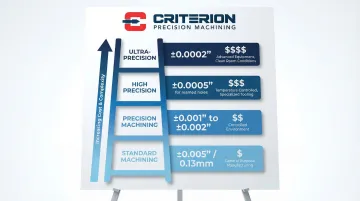
Criterion Precision Machining holds ±0.0002" tolerances across Swiss turning, CNC turning, and milling — a capability built for medical device, aerospace, and defense applications where that level of precision is genuinely required. Specifying it elsewhere adds cost without benefit.
The Five Categories of GD&T Symbols
Form Controls (Shape of Individual Features)
Form tolerances control individual feature shape without referencing datums. They're the most basic geometric controls.
Straightness:
- Controls linear elements of a feature
- Applied to surface elements: controls line elements on the surface
- Applied to axes: controls how straight the centerline is
- Common for shafts, pins, and edges
Flatness:
- Defines two parallel planes within which a surface must lie
- Measured as distance between highest and lowest points
- Critical for sealing surfaces and mounting faces
- Cannot reference datums (it's a form control)
Circularity (Roundness):
- Controls roundness of circular features in a single cross-section
- Measured by rotating part and recording radius variation
- Does not control straightness or taper
- Common for bearing surfaces and O-ring grooves
Cylindricity:
- Combines straightness, circularity, and taper control
- Most restrictive cylindrical control
- Expensive to inspect (requires multiple cross-sections)
- Use only when function demands it
Profile Controls (3D Tolerance Zones Around Surfaces)
Profile tolerances are increasingly popular in modern GD&T because they control both size and form simultaneously.
Profile of a Line:
- Controls profile in a 2D cross-section
- Useful for complex curves and contours
- Creates tolerance zone perpendicular to the true profile
- Measured at individual cross-sections
Profile of a Surface:
- Creates 3D tolerance zone around entire surface
- Most powerful control for complex shapes
- Typical for turbine blades, molded parts, and contoured surfaces
- Requires CMM or optical scanner for verification
Profile verification is one of the more demanding inspection tasks in precision machining — particularly for aerospace and medical components with complex, freeform geometries.
Orientation Controls (Angular Relationships to Datums)
Orientation tolerances control angular relationships between features and datums.
Angularity:
- Controls angle of a feature relative to a datum
- Creates two parallel planes at specified angle
- Does not control location, only orientation
- Common for angled mounting surfaces
Perpendicularity:
- Ensures feature is at 90° to a datum
- Note: 90° angles are assumed unless otherwise specified
- Can apply to surfaces, axes, or planes
- Critical for assembly alignment
Parallelism:
- Controls features that must be parallel to a datum
- Can apply to both surfaces and axes
- Does not control flatness of the feature itself
- Common for mounting rails and guide surfaces
Location Controls (Position Relative to Datums or Other Features)
Location tolerances control where features are located relative to datums or other features.
Position:
- Most commonly used GD&T control
- Defines location using basic dimensions and tolerance zones
- Typically applied at MMC for holes and pins
- Creates cylindrical tolerance zone for features of size
- Enables bonus tolerance when features depart from MMC
Concentricity and Symmetry (Note: Removed from ASME Y14.5-2018):
- Concentricity controlled axis alignment between features
- Symmetry ensured features were symmetrical about a datum plane
- Both were difficult to measure accurately
- Now replaced by Position or Profile controls in ASME standard
- ISO 1101 still retains these definitions
Runout Controls (Variation During Rotation)
Runout tolerances control functional variation of rotating surfaces relative to a datum axis.
Circular Runout:
- Controls variation at single circular cross-section during rotation
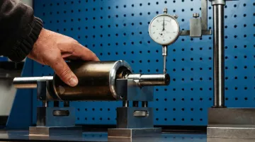
- Measured with dial indicator while part rotates on datum axis
- Controls circularity and coaxiality at that cross-section
- Quick, practical shop-floor measurement
Total Runout:
- Controls entire surface simultaneously during rotation
- Combines circularity, straightness, coaxiality, and taper
- More restrictive than circular runout
- Common for bearing surfaces, sealing surfaces, and rotating components
Total runout is measured by rotating the part on a precision spindle while a dial indicator traverses the entire surface, recording full indicator movement (FIM). Common applications include shafts, pulleys, and any component where rotational accuracy directly affects performance.
Common GD&T Mistakes to Avoid
Over-Constraining Parts
Specifying tighter tolerances than functionally necessary is the primary driver of excess manufacturing costs.
Cost impact:
- Tightening tolerance from ±0.005" to ±0.001" can double manufacturing costs
- Analysis found 30% of features on custom parts had unnecessarily tight tolerances, and adjusting specifications reduced inspection costs by 33%
- Redundant controls create conflicting requirements and increase inspection complexity
Best practices:
- Use general tolerances for non-critical features
- Apply specific GD&T controls only where function requires
- Ask: "What happens if this feature varies more—does the part still work?"
- Consider manufacturing capability when setting tolerances
Improper Datum Selection and Precedence
Tolerance errors aren't always about numbers. Choosing datums based on manufacturing convenience rather than function leads to parts that pass inspection but fail assembly.
Common mistakes:
- Using unstable surfaces that rock or deform as primary datums
- Selecting features with high variability for datum references
- Incorrect datum precedence that doesn't match assembly conditions
- Inaccessible datum features that complicate fixturing
Consequences:
- Ambiguous inspection results with poor repeatability
- Increased scrap due to measurement uncertainty
- Parts that meet drawing requirements but don't assemble correctly
Solution: Simulate assembly conditions when selecting datums. Choose stable, repeatable features that reflect how the part mounts and functions in assembly.
Misunderstanding Material Condition Modifiers
Beyond datums, modifier errors are a common source of inflated costs and scrap. Applying the wrong modifier—or omitting one where it belongs—drives up costs and scrap rates.
Common errors:
- Not specifying material condition when one is appropriate (defaulting to RFS)
- Applying MMC to features without size (invalid per ASME Y14.5)
- Ignoring bonus tolerance opportunities that could allow functional parts to pass
- Using RFS when MMC or LMC would provide functional benefits
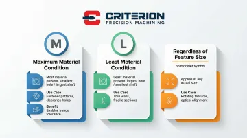
When to use each modifier:
- MMC: Best for fastener patterns and clearance holes, where bonus tolerance can expand allowable variation without affecting fit
- LMC: Use when minimum material must be preserved — thin walls, fragile sections, or features requiring structural integrity
- RFS: Reserve for features where any size variation directly impacts function, regardless of part size
Working with a Machine Shop on GD&T Specifications
Preparing Drawings for Precision Machining
Essential drawing elements:
- Include general tolerance block for features without specific GD&T callouts
- Place GD&T callouts outside part boundaries for clarity
- State applicable standard explicitly ("PER ASME Y14.5-2018" or "PER ISO 1101")
- Add notes about critical features, assembly requirements, or inspection priorities
Model-Based Definition (MBD):
ASME Y14.5-2018 supports embedding tolerances directly in 3D CAD models, reducing translation errors between design and CMM programming. This approach can reduce drawing volume by 90% while improving accuracy.
Communication and Design Review
Early collaboration prevents costly issues downstream. Criterion's estimating process emphasizes collaboration, transparency, and deep understanding of complex parts, covering far more than pricing alone.
Discovery phase benefits:
- Experienced machinists review prints, 3D models, and specifications
- Identify potential GD&T challenges before production begins
- Suggest alternative approaches that maintain function while reducing cost
- Clarify unclear requirements proactively
Many manufacturing issues can be prevented through upfront discussion. Machine shops with precision experience can recommend alternative GD&T approaches, such as using profile instead of multiple individual controls, or applying MMC where appropriate to enable bonus tolerance.
Criterion's quality team reviews drawings for manufacturability and can provide feedback on GD&T specifications, drawing on decades of experience with tight-tolerance components down to ±0.0002" for mission-critical applications.
Inspection and Quality Verification
Once design review is complete, GD&T callouts drive the inspection plan directly. Every control specified on the drawing must be verified using appropriate methods.
Typical inspection methods:
- CMM (Coordinate Measuring Machine): Verifies complex geometry, position tolerances, and profile controls with high repeatability
- Dial indicators: Measures runout on rotating features in-process and during final inspection
- Surface plates with indicators: Confirms flatness and parallelism on prismatic parts
- Optical comparators: Inspects 2D profiles and small features against overlaid templates
- Functional gages: Provide fast pass/fail verification of MMC callouts without CMM time
Criterion's inspection equipment supports comprehensive GD&T verification at production scale:
- Global Advantage CMM with PC-DMIS software: Verifies GD&T specifications and generates detailed inspection reports
- OASIS optical inspection system: Measures multiple dimensions simultaneously for faster throughput
- Keyence vision systems: Captures up to 99 dimensions on up to 100 parts in a single pass
Proper GD&T enables First Article Inspection (FAI) per AS9102 standards and ongoing statistical process control for consistent quality. The ProShop ERP system tracks every operation, tool, and measurement throughout manufacturing, providing full traceability required for ISO 13485 and ISO 9001 compliance.
Frequently Asked Questions
What is GD&T in CNC?
GD&T is a symbolic system used on CNC machining drawings to define the geometry and acceptable variations of part features. It ensures parts are manufactured consistently and function as intended by specifying how features relate to each other geometrically, not just their individual dimensions.
What is the dimensional tolerance for CNC?
CNC machining tolerances vary by process, material, and part geometry — standard machining typically holds ±0.005", while precision machining achieves ±0.001" to ±0.0005" for critical features. Criterion's capabilities reach ±0.0002" for mission-critical applications in medical device, aerospace, and defense.
What is the 3/2/1 rule in GD&T?
The 3-2-1 rule describes how datums constrain degrees of freedom to fully locate a part in 3D space. The primary datum (a plane) constrains 3 degrees of freedom, the secondary (a line or cylinder) constrains 2, and the tertiary (a point) locks the final 1. Together, they establish a repeatable coordinate system for manufacturing and inspection.