The CNC machining and turning centers market was valued at $25.9 billion in 2023 and is projected to reach $40.6 billion by 2030 — a figure that reflects how central turning operations are to modern precision manufacturing. From aerospace engine fittings to medical implant components, CNC lathes sit at the core of mission-critical production.
This guide covers the four essentials: how a CNC lathe works, its key components, the operations it performs, and the machine types available.
Key Takeaways
- CNC lathes rotate the workpiece while a stationary tool removes material — ideal for cylindrical parts.
- Core components: headstock, spindle, chuck, carriage, tool turret, and tailstock.
- Standard operations include turning, facing, threading, boring, grooving, and taper turning.
- Configurations range from basic 2-axis lathes to Swiss turning centers that hold sub-0.010" diameters.
- Aerospace and medical parts routinely require tolerances of ±0.0002" — achievable on modern CNC turning equipment.
How a CNC Lathe Works
The Basic Motion Principle
The workpiece is clamped in a chuck and rotated about the Z-axis — this is the primary motion. The cutting tool moves linearly along the X and Z axes (the feed motion), contacting the spinning part and removing material in controlled passes. ISO 841:2001 defines this axis convention directly: Z runs parallel to the principal spindle, while X is radial and parallel to the cross-slide, with positive X pointing away from the rotational axis.
The CNC Lathe Cycle
A typical production cycle follows five steps:
- Mount and clamp — the operator loads the workpiece into the chuck or collet
- Spindle rotation — the CNC control accelerates the spindle to the programmed speed
- Tool engagement — the turret indexes to the correct tool; the tool moves along the programmed path
- Material removal — the tool traces the geometry defined in the CNC program
- Finishing operations — boring, threading, grooving, or other secondary operations complete the part
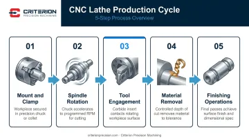
No manual intervention occurs during the cut. Everything runs from G-code or CAM-generated programs.
For complex multi-operation parts, programs are developed offline in CAD/CAM software. For simpler setups, conversational interfaces — like FANUC's MANUAL GUIDE i — let operators build programs directly at the machine without writing G-code by hand.
Axis Configurations and Capability Tiers
The production cycle described above only reflects what a 2-axis machine can do. Add more axes, and the capability expands considerably:
| Configuration | Axes | Capability |
|---|---|---|
| 2-axis | X + Z | OD/ID turning, facing |
| 3-axis | + C-axis with live tools | Milling slots, drilling, tapping in one setup |
| 4-axis | + Y-axis | Off-center operations |
| 5-axis+ | + sub-spindle or second turret | Complete front-and-back machining without re-chucking |
A sub-spindle lets the machine complete both ends of a part without re-chucking, which directly improves dimensional consistency and cuts cycle time on complex components.
Key Parts of a CNC Lathe Machine
Machine Bed
The bed is the structural foundation everything else mounts to. High-grade cast iron is standard because it damps vibration and resists thermal distortion. Integrated guideways — either box guides or linear rails — control how the carriage and tailstock travel, and their precision directly limits what tolerances the machine can hold.
Headstock and Spindle
The headstock houses the main drive motor, gearbox, and spindle assembly. The spindle drives workpiece rotation, establishes the C-axis for live-tool operations, and determines the upper limit of achievable tolerance and surface finish. Spindle quality sets the ceiling on tolerance, surface finish, and repeatability.
Chuck, Collet, and Workholding
The chuck attaches directly to the spindle face and clamps the workpiece. Common types:
- 3-jaw chuck — self-centering, fast setup, suited for round stock
- 4-jaw chuck — independent jaw adjustment, used for irregular or off-center workpieces
- Hydraulic chuck — power-actuated, consistent clamping force, preferred for production runs
Collets are the alternative for smaller-diameter, bar-fed work. They grip with higher concentricity than chucks, making them the preferred workholding for tight-tolerance medical and aerospace components where every micron of runout matters.
Carriage and Tool Turret
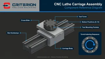
The carriage rides along the bed guideways and carries the cutting tool assembly. The cross-slide within the carriage provides radial tool movement for facing and form operations. Mounted on the carriage, the turret holds multiple cutting tools — roughly 6 to 24 stations depending on the machine — and indexes automatically between operations without stopping the cycle. On high-mix production lines, that automatic indexing directly reduces non-cut time per part.
Tailstock
The tailstock supports the far end of long or slender workpieces — shafts, rods, thin spindles — that would otherwise deflect under cutting forces. On modern CNC lathes, the tailstock can be programmed in semi-auto mode and retracts automatically for face-turning operations.
CNC Lathe Operations and Processes
Turning, Facing, and Contour Turning
Straight turning moves the tool along the Z-axis to reduce diameter or create cylindrical profiles — the most fundamental CNC lathe operation. Facing moves the tool radially across the end of the workpiece to create a flat, perpendicular surface.
Contour turning programs a non-linear path to generate curved profiles. This is common in aerospace connectors and hydraulic fittings where complex external geometries need to be turned in a single pass rather than manually blended.
Threading and Taper Turning
Threading feeds a pointed tool longitudinally at a feed rate synchronized with spindle rotation — cutting external or internal threads precisely. The synchronization is handled entirely by the CNC control; the operator programs the pitch and the machine maintains it consistently across every pass.
Taper turning angles the tool path to produce conical shapes. Medical bone screws, aerospace fasteners, and hydraulic fittings all rely on taper turning for their tapered lead geometries.
Boring, Drilling, and Reaming
Three related but distinct internal operations:
- Drilling — feeds a rotating drill into the spinning part along the central axis to create a hole
- Boring — enlarges an existing hole using a single-point tool fed parallel to the Z-axis, achieving tighter tolerances and better surface finish than drilling alone
- Reaming — follows boring to refine the bore to final tolerance with a consistent surface finish
Sandvik Coromant defines boring as the process for achieving close hole tolerance and high-quality surface finish. This sequence is the standard approach for precision bores in valve bodies, bushing housings, and implant components.
Grooving, Parting, Chamfering, and Knurling
- Grooving — plunges the tool radially to cut grooves for O-rings, retaining clips, or sealing features
- Parting — extends grooving to separate a finished component from bar stock
- Chamfering — breaks sharp corners using the tool edge, required on virtually every production part
- Knurling — a forming operation (not a cutting operation) that presses a cross-hatch pattern onto the surface for grip; used on instrument handles and adjustment knobs
Tolerance and Quality Control
Every operation described above is only as good as the tolerances it holds. Achieving ±0.0002" requires correct cutting tool selection (carbide inserts, ceramics, or coated tools matched to the material), proper speeds and feeds, and active coolant management — alongside rigorous inspection at each production stage.
Criterion Precision Machining's certified QA program covers all four inspection stages: incoming material, first article, in-process, and final. The inspection suite includes:
- Global Advantage CMM with PC-DMIS software for dimensional verification
- OASIS Optical Automatic Smart Inspection System for non-contact measurement
- Keyence IM 6225 Image Dimension Measurement System capable of measuring up to 99 dimensions simultaneously
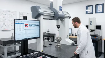
Every regulated-industry shipment ships with a full documentation package.
Types of CNC Lathes
Horizontal vs. Vertical CNC Lathes
Horizontal CNC lathes are the most common configuration. The spindle runs horizontally, the workpiece rotates on a horizontal axis, and gravity assists chip evacuation. This setup handles the vast majority of turned components across all industries.
Vertical CNC lathes orient the spindle vertically, with the workpiece sitting on a large rotating table. They're purpose-built for very large-diameter, heavy parts — turbine rings, flanges, large housings — where horizontal clamping would be impractical or unsafe.
Swiss-Type CNC Lathes
Swiss-type lathes operate on a different mechanical principle. The workpiece feeds through a guide bushing while tools work immediately adjacent to the support point. This arrangement eliminates deflection on slender parts, enabling extremely small-diameter components — typically under 32 mm, with some machines handling up to 38 mm — to be machined to tolerances impossible on a conventional lathe.
Swiss turning is the method of choice for:
- Medical devices: bone screws, catheter tips, surgical pins, implantable device components
- Photonics hardware: lens mounts, optical housings, beam delivery components
- Precision sensors: small-diameter sensor bodies requiring features as small as 0.010"
Criterion Precision Machining operates three Swiss turning centers — a 5-axis, 6-axis, and 8-axis machine, all with live tooling. The shop's Swiss turning capability covers bar diameters from 0.04" to 0.875", produces features as small as 0.010", and holds tolerances to ±0.0002" throughout that range.
CNC Lathe Materials and Applications
Materials
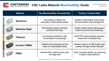
CNC lathes process a wide range of materials, each with distinct machinability characteristics:
- Aluminum — high cutting speeds, long tool life with sharp-edged inserts
- Stainless steel — requires coolant to control chip formation and prevent work hardening
- Titanium — low thermal conductivity demands coolant-fed tooling and aggressive chip control
- Inconel and HRSA alloys — high-pressure precision coolant improves tool life on aerospace-grade superalloys
- PEEK — biocompatible engineering plastic requiring precise control of heat, feed rate, and tooling geometry to prevent microfractures
Criterion also machines specialty alloys including Hastelloy, Nitinol, and cobalt-chrome — materials that appear frequently in medical implants, defense systems, and photonics assemblies. These additions extend capability into some of the most demanding material families in precision manufacturing.
Applications by Industry
| Industry | Typical Turned Components |
|---|---|
| Aerospace | Sensor housings, actuation system components, structural brackets |
| Medical devices | Implantable device housings, surgical instrument bodies, endoscopic components |
| Defense | Suppressor housings, buffer assemblies, optical housings for tactical equipment |
| Photonics & optics | Lens mounts, laser system components, optical bench assemblies |
For regulated industries, material traceability is non-negotiable. Criterion's ISO 13485 and ISO 9001 certifications require that mill certifications, certificates of conformance, and first article inspection reports accompany every delivered component.
CNC Lathe vs. Manual Lathe
Choosing between CNC and manual depends on volume, complexity, and the value of operator time. The table below breaks down the key differences:
| Factor | CNC Lathe | Manual Lathe |
|---|---|---|
| Control method | Programmed G-code / CAM | Operator-controlled handwheels |
| Precision | Consistent, repeatable tolerances | Operator-skill dependent |
| Production speed | High throughput; one operator, multiple machines | Slower; one-on-one attention required |
| Operator skill required | Programming and setup expertise | Deep machining craft knowledge |
| Ideal use case | Production volumes, complex geometries | One-off prototypes, simple repairs |
CNC lathes dominate production environments because of programmed repeatability — the machine duplicates commanded motions consistently across every unit in the run. Manual lathes still hold value for certain repair work and one-off applications where setup time outweighs the programming investment.
Frequently Asked Questions
What is a CNC lathe machine?
A CNC lathe is a computer-controlled machine tool that rotates a workpiece on a spindle while a stationary cutting tool removes material to produce cylindrical or symmetrical shapes. All movements are guided by programmed G-code instructions, eliminating manual operator intervention during the cut.
What does a CNC lathe machinist do?
A CNC lathe machinist sets up and operates CNC turning equipment. Core responsibilities include:
A CNC lathe machinist sets up and operates CNC turning equipment. Core responsibilities include:
- Loading workpieces and selecting or mounting cutting tools
- Writing or loading CNC programs
- Performing first-article dimensional verification
- Monitoring production runs to confirm parts meet dimensional and surface finish specifications
What operations can be performed on a CNC lathe?
Core operations include turning, facing, threading, boring, drilling, grooving, parting, taper turning, chamfering, and knurling. Multi-axis turning centers with live tooling also perform milling, tapping, and off-center drilling — all in a single setup.
What is the difference between a CNC lathe and CNC milling?
In CNC turning, the workpiece rotates and the tool moves linearly — suited for cylindrical parts. In CNC milling, the tool rotates and the workpiece is stationary — suited for prismatic and complex-surface parts. Many advanced turning centers combine both capabilities through live tooling and Y-axis movement.
What materials can be machined on a CNC lathe?
Common materials include aluminum, stainless steel, carbon steel, titanium, Inconel, brass, and engineering plastics like PEEK. Material selection depends on the application's requirements for strength, weight, biocompatibility, and corrosion resistance.
What tolerances can a CNC lathe achieve?
Standard CNC turning holds ±0.001" for general precision work. High-end Swiss turning centers used in aerospace and medical applications can achieve tolerances as tight as ±0.0002", depending on machine quality, tooling, material, and process control. Criterion Precision Machining, for example, routinely holds ±0.0002" for medical device and aerospace components.