Introduction
In aerospace, medical devices, and defense, dimensional tolerances carry real consequences. A deviation of a few ten-thousandths of an inch in a surgical implant or actuator shaft can cause a system to fail under load — not theoretically, but in service.
"High precision" in CNC turning describes a specific capability gap between standard commercial machining and the controlled process chains required for critical applications. According to a 2024 study in Manufacturing Letters, thermal errors alone can account for up to 75% of total machine-tool error — which means even a well-programmed part can fall out of tolerance if the full process isn't managed.
This article covers what separates high-precision CNC turning from standard turning, the step-by-step process, best practices that protect tight tolerances, inspection methods that verify them, and the industries that demand them. If you're specifying tolerances in the ±0.0002″ range or qualifying a new machining partner, the process controls covered here are what to look for.
Key Takeaways
- High-precision CNC turning holds tolerances tighter than ±0.001"; specialized setups reach ±0.0002", but only when the full process chain is controlled
- Precision depends equally on workholding, tooling, cutting parameters, thermal management, and inspection — not the machine alone
- Material selection directly affects achievable tolerance: titanium, stainless, and PEEK each require distinct strategies
- Multi-point inspection throughout production distinguishes quality-assured shops from those relying solely on end-of-line checks
- ISO 9001 and ISO 13485 certifications signal documented, auditable processes — the baseline for regulated industry suppliers
What Is High-Precision CNC Turning?
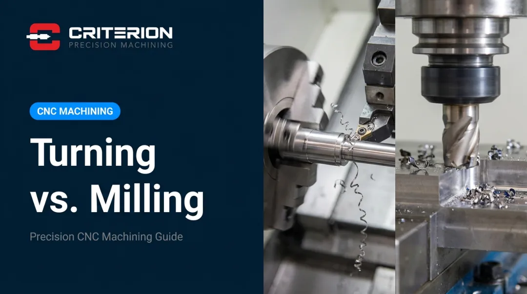
CNC turning is a subtractive process in which a workpiece rotates on a spindle while a stationary cutting tool removes material along programmed paths. It produces cylindrical, conical, threaded, and complex rotational geometries. The key distinction from CNC milling: in turning, the workpiece rotates; in milling, the tool rotates.
High-precision turning differs from standard commercial turning across three dimensions: tighter tolerance bands, stricter surface finish requirements, and more rigorous roundness and concentricity controls. The numbers bear this out:
| Grade | Tolerance | Notes |
|---|---|---|
| Standard CNC machining | ±0.005" | Protolabs benchmark |
| Precision CNC machining | ±0.002" | Protolabs benchmark |
| Reamed holes | ±0.0005" | With proper fixturing and tooling |
| Axis repeatability | 0.000030" | Hardinge T-Series turning centers |
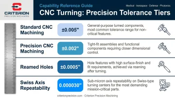
These numbers only materialize when the entire process — programming, setup, tooling, thermal management, and inspection — is controlled as a system.
Conventional CNC Turning vs. Swiss CNC Turning
Swiss-style CNC turning uses a sliding headstock and a guide bushing that supports the workpiece very close to the cutting zone. Rather than the tool traveling to the part, the workpiece advances through the bushing while tools remain fixed. This configuration dramatically reduces deflection on long, slender parts.
Citizen Machinery identifies Swiss turning as particularly suited to medical instruments, aerospace actuators, fiber optics components, and defense fasteners. Star GB lists bar capacities from 10 mm up to 42 mm — making Swiss turning the right choice for small-diameter, high-aspect-ratio components where standard chucking would introduce unacceptable runout.
Swiss turning configurations vary widely in axis count and capability. Criterion Precision Machining runs 5-axis, 6-axis, and 8-axis Swiss turning centers with live tooling, capable of working diameters from 0.010" to 0.875" and holding tolerances to ±0.0002". The live tooling capability means milling, drilling, and turning can happen in a single setup — critical for complex micro-components that can't tolerate multiple handling steps.
The High-Precision CNC Turning Process, Step by Step
Step 1 — CAD Design and DFM Review
Precision starts before a machine is turned on. Engineers develop a 3D CAD model with full GD&T callouts specifying tolerances, surface finishes, and geometric controls. A Design for Manufacturability (DFM) review then identifies features that are difficult to hold to tight tolerance — thin walls, long overhangs, deep internal bores — and allows design modifications before any cutting begins. Catching these issues at the drawing stage costs far less than discovering them mid-run.
Step 2 — CAM Programming and Toolpath Optimization
The CAD model is translated into machine instructions (G-code) via CAM software. For high-precision turning, toolpath strategy directly affects dimensional outcome. Climb cutting, controlled lead-in/lead-out moves, and reduced depth of cut on finishing passes all contribute to better dimensional accuracy and surface finish.
Criterion uses Autodesk PartMaker®, CAM software built specifically for Swiss-style lathes, to optimize cycle times and consistency across production runs.
Step 3 — Machine Setup and Workholding
Any misalignment introduced during setup propagates directly into dimensional error. Workpieces are mounted in collet chucks or jaw chucks, then aligned using a dial indicator. Collet chucks are generally preferred over jaw chucks for round stock in precision work (better concentricity, more consistent clamping force).
Setup also includes:
- Tool installation and offset entry
- Verification cut before production begins
Step 4 — Roughing and Finishing Passes
High-precision turning uses a two-stage strategy:
- Roughing passes remove bulk material quickly, leaving a controlled amount of stock (typically a few thousandths of an inch) for finishing
- Finishing passes use sharp tools, lower feed rates, and finer depths of cut to achieve final dimensions and surface finish
Single-pass approaches rarely work for tight-tolerance turning. The roughing pass relieves internal stresses and brings the part close to final geometry; the finishing pass, done with fresh tooling and optimized parameters, hits the tolerance band.
Step 5 — In-Process and Post-Process Inspection
Measurement is built into the process, not bolted on at the end. In-process dimensional checks catch drift before it becomes scrap. Post-process CMM inspection verifies the final part against nominal geometry. The inspection workflow is covered in depth in its own section below.
Best Practices for Achieving Tight Tolerances in CNC Turning
Cutting Tool Selection and Condition
Tool material, geometry, and condition directly affect both dimensional accuracy and surface finish. Sandvik identifies flank wear as the primary cause of dimensional tolerance degradation, while crater wear weakens the cutting edge and increases the risk of sudden failure.
Running tools to failure is not a precision strategy. The better approach:
- Establish a tool change protocol based on a defined surface finish limit or part count — typically changing 10–20% before expected deterioration begins
- Use coated carbide grades (CVD-coated with alpha-alumina layers) for crater and flank wear resistance in steel and titanium
- Use sharp, positive-geometry inserts for aluminum; PCD grades where silicon content exceeds 13%
Optimizing Cutting Parameters by Material
Cutting parameters aren't universal — they're material-specific. Published toolmaker data shows distinct ranges for each:
| Material | Roughing Speed | Finishing Speed | Key Risk |
|---|---|---|---|
| Titanium | 50–100 m/min | 80–150 m/min | Heat concentration, tool failure |
| Austenitic stainless | 120–200 m/min | 180–300 m/min | Work hardening, built-up edge |
| Aluminum (wrought) | 120–700 m/min | 120–700 m/min | Built-up edge at low speeds |
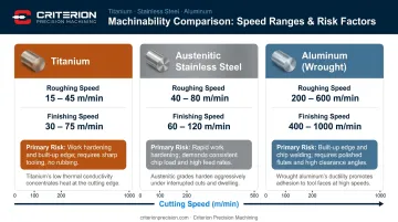
Titanium's poor thermal conductivity concentrates heat in the cutting zone; high-pressure coolant of at least 500 psi is non-negotiable. Stainless steel work-hardens if the tool dwells or the feed rate drops too low. Aluminum forms built-up edge at slow speeds, which smears and ruins surface finish.
Run test cuts before a full production run to confirm the parameter set holds tolerance.
Vibration and Chatter Control
Seco Tools defines chatter as self-exciting resonant vibration that occurs when cutting forces excite the natural frequency of the tool or workpiece. The result is surface waviness, dimensional scatter, and accelerated tool wear.
Mitigations that work:
- Minimize tool overhang — shorter is always more rigid
- Use anti-vibration toolholders (Sandvik Silent Tools support overhangs up to 14× bar diameter)
- Ensure workpiece support with tailstock or steady rests on long, slender parts
- Adjust spindle speed to move away from resonance frequencies
Thermal Management and Dimensional Stability
Once vibration is under control, thermal effects become the next dimensional variable to manage. ISO 1:2022 fixes the standard reference temperature for dimensional measurement at 20°C because metals expand with heat — and during a long turning cycle, thermal growth of the spindle, tool, and workpiece can shift dimensions by measurable amounts.
Practical controls:
- Flood coolant or through-tool coolant to manage cutting-zone temperature
- Thermal warm-up cycles before starting precision cuts — allow the machine to reach equilibrium
- Temperature-controlled environments in shops where the tightest tolerances are routine
Machine Calibration and Preventive Maintenance
Axis positioning accuracy, spindle runout, and geometric alignment drift over time. A machine that was qualified to spec last year may not hold the same tolerances today without intervention.
Calibration methods that matter:
- Ballbar testing — evaluates circular motion accuracy and reveals servo lag, backlash, and geometric errors
- Laser interferometry — measures linear positioning accuracy and repeatability along each axis
- Regular bearing checks, lubrication, and guideway inspection prevent the mechanical degradation that shows up as dimensional scatter
For shops holding tolerances in the ±0.0002" range — common in medical device and aerospace work — quarterly ballbar checks and annual laser interferometry verification are typically the minimum to sustain rated machine accuracy.
Inspection and Quality Verification in Precision CNC Turning
Inspection in high-precision CNC turning is a planned series of verification points integrated throughout the process — not a single final check before shipment.
Criterion's inspection workflow follows four defined stages:
- Incoming material verification — raw material is checked and documented before machining begins
- First Article Inspection (FAI) — a comprehensive dimensional check of the first part produced validates the setup against all drawing requirements
- In-process inspection at the machine — dimensional checks during production catch drift before it creates non-conforming parts
- Final inspection before shipment — every order is verified against specifications before release

CMM and Dimensional Verification Equipment
A Coordinate Measuring Machine (CMM) is the standard tool for comprehensive dimensional verification. It probes the part surface at programmed points, mapping actual dimensions against nominal CAD geometry to capture true position, roundness, cylindricity, and concentricity. Hand gauges cannot reliably capture this level of geometric data.
Criterion operates a Global Advantage 5×5×5mm CMM with a TESTASTAR-sm® motorized probe head, running PC-DMIS software. PC-DMIS generates repeatable measurement programs, verifies customer GD&T callouts, and produces formal inspection reports that travel with the shipment.
Hexagon's PC-DMIS 2024.2 and later versions verify GD&T and highlight detected errors automatically.
CMM sampling density matters for tight tolerances. Mitutoyo recommends 24 measurement points for tolerances under 0.0005", and 16 points for tolerances under 0.002". Most shops running quick checks use far fewer points, which is where tolerance drift goes undetected.
Optical and Multi-Dimensional Inspection Systems
Criterion uses two additional inspection systems alongside the CMM:
- OASIS Optical Automatic Smart Inspection System — a non-contact video profile measurement system that measures multiple dimensions simultaneously. Particularly effective for small, complex components where contact probing could risk damage, and for rapid verification during production runs
- Keyence IM-6225 Image Dimension Measurement System — capable of measuring up to 99 dimensions on up to 100 parts simultaneously, enabling high-throughput inspection without sacrificing accuracy
Together, CMM handles comprehensive GD&T verification, OASIS covers simultaneous profile measurement, and Keyence enables rapid in-process confirmation. For regulated industries, that combination means dimensional problems get caught at the machine — not during final audit or after delivery.
What Certifications Mean for Buyers
Criterion holds ISO 9001:2015 and ISO 13485:2016 certifications, and is FDA registered and ITAR registered. For buyers, these aren't just credentials — they represent documented, audited quality systems.
Under ISO 13485, medical device component shipments from Criterion include:
- Certificates of Conformance (CoC), provided at no charge
- Material certifications with shipping documents
- Final inspection reports
- First Article Inspection Reports (FAIRs), available for regulated programs
- Full traceability records through ProShop ERP
For aerospace programs, First Article Inspection documentation follows SAE AS9102 requirements. Every operation, tool, and measurement is tracked in ProShop ERP, giving auditors and customers a complete, retrievable quality record.
Industries That Demand High-Precision CNC Turned Parts
Medical Devices
Surgical instruments, implant components, and catheter-related parts require surface finishes and dimensional tolerances that are both performance-critical and FDA-mandated. An out-of-tolerance implant component can cause patient harm.
ISO 13485 certification is the baseline qualification for any shop serving this sector. It requires documented traceability from raw material through final shipment, a standard the FDA QMSR has incorporated into its device QMS regulation.
Criterion serves medical device customers including Riverpoint Medical and Smith & Nephew, producing components like surgical pins, orthopedic fasteners, and implantable device parts on its Swiss turning and CNC turning platforms.
Aerospace and Defense
Aerospace components — actuator shafts, hydraulic fittings, sensor housings, guidance system parts — operate under AS9100 or customer-specific quality requirements.
Key compliance standards governing this work include:
- NASA-HDBK-8739.18: Governs management of nonconformances in flight hardware
- SAE AS9102: Boeing's First Article Inspection standard for purchased hardware
- AS9100: Quality management baseline for aerospace suppliers
Defense and ITAR-controlled work adds supply chain security requirements on top of dimensional precision. Criterion's ITAR registration, DFARS compliance, and in-progress CMMC certification position the company to handle the full documentation and compliance scope that defense programs require.
Photonics and Optics
Precision-turned housings, lens mounts, and optomechanical components for laser systems and optical instruments often require concentricity and surface finish specifications beyond what most machine shops can hold. Even small geometric deviations can misalign an optical path and degrade system performance — as SPIE optomechanical design guidance documents in its treatment of lens-to-mount interface stress and alignment tolerance.
Criterion machines lens housings, lens mounts, optical benches, and sensor enclosures for photonics customers including Corning, holding ±0.0002″ tolerances and tight concentricity to ensure optical bores remain true to outer diameters after assembly. At that tolerance level, there's no margin for process drift or inconsistent fixturing.
Frequently Asked Questions
How precise can CNC turning be?
Standard commercial CNC machining typically holds ±0.005". Precision CNC turning reaches ±0.002" or tighter, with specialized setups achieving ±0.0005" on features like reamed holes. Swiss turning centers can reach ±0.0002" on small-diameter parts, provided tooling, thermal management, and inspection are all controlled together.
What is the difference between CNC turning and Swiss CNC turning?
Standard CNC turning uses a fixed spindle with a chuck; the tool travels to the workpiece. Swiss turning uses a sliding headstock and guide bushing that supports the workpiece close to the cutting zone, dramatically reducing deflection on long, slender parts. Swiss turning is the right choice for small-diameter components — typically under 1" — in medical devices, defense, and photonics applications.
What tolerances are typically required for aerospace and medical CNC turned parts?
Tolerance requirements are specified per engineering drawing and vary by application — there's no single answer. Medical and aerospace drawings commonly carry tighter GD&T callouts than commercial work, particularly for features like bore diameter, concentricity, and true position. Reviewing the actual drawing with a qualified machining partner is the only reliable way to determine what's achievable for a specific component.
How do you maintain tolerance consistency across a production run?
Consistency requires in-process gauging at defined intervals, scheduled insert changes, and Statistical Process Control (SPC) to catch process drift before it produces non-conforming parts. Periodic mid-run re-inspection — beyond first article and final — is what catches gradual dimensional shifts before they affect the entire batch.
What materials are best suited for high-precision CNC turning?
Aluminum, stainless steel, titanium, and engineering plastics like PEEK are the most common high-precision turning materials. Aluminum and stainless machine predictably with proper parameters; titanium requires aggressive coolant strategies due to poor thermal conductivity. PEEK requires reduced clamping forces and sharp tooling to prevent distortion.
What certifications should I look for in a precision CNC turning shop?
ISO 9001 is the baseline quality management certification. ISO 13485 is required for medical device component suppliers. ITAR registration is mandatory for defense and weapons-related work. FDA registration applies to shops producing medical device components. Each certification represents documented, audited processes and quality records that regulated industries require — not just a badge on a website.