Introduction
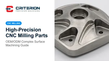
When a contoured mating surface is off by a few microns, you don't get a warning — you get an assembly failure, a regulatory rejection, or a field incident. High-precision CNC milling for complex surfaces is computer-controlled subtractive machining that produces multi-dimensional, non-planar part geometries to tolerances as tight as ten-thousandths of an inch.
For OEM engineers and procurement leads in aerospace, medical device, defense, and photonics, this process is a requirement. These are "No Failure" industries, where a deviation across a contoured mating surface can cascade into assembly failure, regulatory rejection, or a safety incident.
Standard milling handles prismatic geometry. Complex surface milling handles everything else: the compound curves on an orthopedic implant, the aerodynamic contours on a structural bracket, the micron-level flatness of an optical mount.
Getting that geometry right — consistently, across a full production batch — is what separates a qualified supplier from a capable one. This guide covers the process, toolpath strategies, material considerations, and quality requirements that matter when the geometry can't be compromised.
Key Takeaways
- 5-axis CNC milling adds rotational axes to reach complex curved and undercut geometry inaccessible from a single orientation
- Tolerances down to ±.0002" are achievable — but only with the right combination of machine capability, toolpath strategy, fixturing, and inspection
- ODM engagements demand deeper design-for-manufacturability expertise than standard OEM supply relationships
- Material choice (titanium, stainless, PEEK, aluminum) directly determines cutting strategy and realistic tolerance targets
- Certifications matter: ISO 13485, ISO 9001, ITAR registration, and FDA registration confirm documented, audited processes
What Is High-Precision CNC Milling for Complex Surfaces?
High-precision CNC milling uses computer-controlled, multi-axis cutting tools to remove material from solid stock, producing complex part geometries — freeform surfaces, compound curves, undercuts, and tight-radius contours — while holding dimensional tolerances as tight as ±.0002".
The goal is functional surfaces. Surfaces that mate, seal, articulate, or perform under load exactly as engineered. Any deviation across the surface profile — not just at datum features — affects whether the part can do its job.
How It Differs from Standard Milling
Standard 3-axis CNC milling moves a cutting tool in X, Y, and Z — sufficient for prismatic geometry like flat faces, bored holes, and slots. What it cannot do is reach geometry that requires the tool to approach from multiple angles without re-clamping.
Complex surface milling adds rotational and tilting axes. As DMG MORI describes, 5-axis machines add two rotary axes to the standard three linear ones — allowing the tool to approach the workpiece from virtually any angle. The practical result:
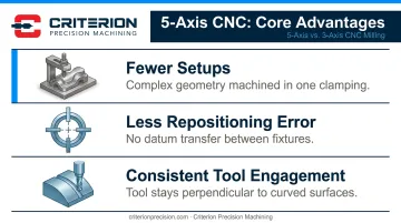
- Fewer setups — complex geometry machined in one clamping
- Less repositioning error — no datum transfer between fixtures
- Consistent tool engagement — the cutter stays perpendicular to curved surfaces, maintaining chip load and finish across the entire contour
For parts where surface profile tolerance applies across the entire geometry — not just at a few measurement points — this distinction is everything.
Why OEM/ODM Manufacturers in "No Failure" Industries Depend on Complex Surface Milling
The OEM/ODM Distinction Matters Here
OEM manufacturers receive complete engineering specifications. The machining partner's job is accurate execution. ODM manufacturers contribute to design intent — which means the machining partner needs to understand not just the geometry, but the functional requirement driving it. That demands design-for-manufacturability expertise, not just spindle hours.
What "No Failure" Industries Require
Each sector brings specific surface geometry requirements that complex milling directly addresses:
- Aerospace — aerodynamic surface profiles, compound fillets on structural brackets, tight geometric callouts for mating hardware
- Medical device — biocompatible surfaces on implant articulating faces, specified finish and dimensional form on instrument handles
- Defense — repeatable geometry on housings and mounting features that must perform under extreme environmental stress
- Photonics — surface accuracy measured in microns on lens mounts and optical alignment fixtures
What Goes Wrong Without It
Parts machined across multiple setups accumulate error at each re-fixturing. ASME's tolerance analysis research identifies setup-related datum transformation as a distinct error source in multi-setup machining plans — separate from local cutting errors. On complex surface geometry, those accumulated errors show up as:
- Assembly misalignment
- Fluid or pressure leaks at mating faces
- Fit failure at tight-tolerance interfaces
- Regulatory rejection at first article inspection
How Certifications Translate to Audited Process Controls
That last failure mode — regulatory rejection — is where certification requirements become directly relevant. In FDA-regulated and aerospace-certified supply chains, complex surface milling with in-process inspection is how documented process controls are implemented and verified.
ISO 13485:2016 (the medical device quality management standard) requires control of production and service provision processes, with traceability from raw material to finished part. ISO 9001:2015 governs equivalent documentation requirements across other regulated sectors. A machining partner who holds these certifications has had their process controls verified by third-party auditors — not self-declared.
How High-Precision CNC Milling for Complex Surfaces Works
The End-to-End Flow
A 3D CAD model is translated by CAM software into a multi-axis toolpath. The machine executes that path with the part fixtured. In-process probing verifies critical features mid-cycle. Post-machining inspection verifies surface profiles, positional tolerances, and finish against GD&T callouts before the part ships.
The inputs for this process:
- Engineering drawing with GD&T surface profile callouts (per ISO 1101)
- Material stock selected for the application
- Cutting tools chosen for geometry and finish requirements
- Fixturing designed for multi-axis stability
- Programmed toolpath from CAM software
Step 1: CAD/CAM Programming and DFM Review
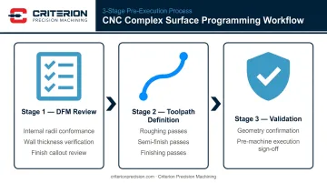
Before programming begins, the part model is reviewed for manufacturability. Three factors get scrutinized early:
- Internal radii must accommodate the intended tool diameter
- Wall thicknesses must withstand cutting forces without deflection
- Surface finish callouts must map to specific finishing pass strategies
Programmers then define roughing, semi-finish, and finishing toolpaths that progressively approach final geometry. Sandvik Coromant's profile milling guidance covers strategies including waterline milling and Z-constant contouring for 3- to 5-axis work. For finishing passes, ball-nose end mills control scallop height through stepover distance and feed per tooth. The objective throughout is minimizing residual stress and deflection before the finishing pass locks in final geometry.
Once the toolpath is validated, execution moves to the machine.
Step 2: Multi-Axis Machining Execution
4- and 5-axis CNC machines execute the toolpath, positioning the cutting tool relative to complex surface geometry without re-clamping. Haas confirms that 5-axis machines support both 3+2 indexed positioning (holding a fixed angle for a defined feature) and simultaneous 5-axis motion (moving rotary and linear axes continuously during cutting).
Criterion's 5-axis CNC milling capabilities — including HAAS UMC 500 SS machines — enable this level of complex surface execution while holding tolerances down to ±.0002" for critical surface features. Parts ranging from .25" square up to 17" × 22" × 17" fall within the production envelope.
Step 3: In-Process Probing and Final Inspection
Renishaw's machine-tool probing systems support in-cycle gauging that checks critical features while the part is still fixtured — allowing offset corrections before finishing passes lock in final geometry.
Post-machining, Criterion's inspection infrastructure includes:
- Global Advantage CMM with PC-DMIS software — verifies surface profiles and GD&T positional callouts, generating full traceability documentation
- OASIS Optical Automatic Smart Inspection System — non-contact, multi-dimensional simultaneous measurement for complex geometries
- Keyence measuring systems — measures up to 99 dimensions simultaneously, supporting high-throughput verification
- SPC software — supports process capability data generation for production runs
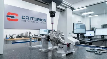
Every inspection record feeds traceable documentation required for regulated industry release.
Key Factors That Affect Precision in "No Failure" Industry Parts
Machine capability is necessary but not sufficient. Outcomes depend on the interaction of materials, conditions, equipment, and constraints.
Inputs and Materials
| Material | Machining Challenge | Implication for Complex Surfaces |
|---|---|---|
| Titanium | Work hardening, tool deflection | Lower speeds, higher rigidity required across curved geometry |
| Stainless steel | Heat generation, tool wear | Controlled feeds prevent dimensional drift on contoured passes |
| PEEK | Heat sensitivity, surface smearing | Sharp tools, controlled heat to preserve dimensional geometry |
| Aluminum | Part movement at high speeds | Careful fixturing for aggressive multi-axis passes |
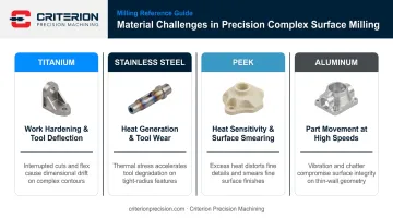
Kennametal's titanium milling guidance specifically identifies tool deflection as a machining risk and recommends adjusting feeds and speeds to manage it. On curved geometry, that deflection translates directly to surface profile error — which is why material-specific toolpath parameters matter as much as machine selection.
Operating Conditions
Two environmental factors routinely compromise dimensional accuracy on complex surface programs:
- Thermal expansion: Long machining cycles cause dimensional drift. NIST research confirms thermal effects as a primary accuracy driver in CNC machining. Climate-controlled environments and thermal compensation in modern CNC controllers reduce this risk — but it remains significant in titanium and stainless programs.
- Vibration: Spindle imbalance or adjacent machinery amplifies surface finish deviation across large contoured areas. Fixturing rigidity matters as much as machine rigidity in controlling this.
Scale and Process Capability
Prototype runs allow toolpath iteration and first-article verification. Production runs require something more: documented evidence that tolerance is maintained across the full batch, not just the first part. Look for a partner who provides SPC-based process capability data as part of their quality package — not just a certificate of conformance on part one.
Regulatory and Safety Constraints
| Certification / Registration | What It Confirms |
|---|---|
| ISO 13485:2016 | QMS with traceability from raw material to finished part for medical device supply chains |
| ISO 9001:2015 | Documented, audited process controls across all production operations |
| ITAR Registration | DDTC requires registration for any US manufacturer of defense articles — even without export |
| FDA Registration | Required for establishments producing medical devices for US commercial distribution |

In regulated supply chains, audited process documentation carries more weight than equipment lists. Confirm your machining partner holds the certifications specific to your industry before the first order, not after a nonconformance.
Common Misconceptions and When Complex Surface CNC Milling Isn't the Right Fit
More Axes ≠ More Precision
A 5-axis machine programmed with an unoptimized toolpath, run without in-process inspection, produces no better results than a well-controlled 3-axis process. The axis count determines what geometry is reachable — not what tolerance is achievable. Precision comes from the system: machine, toolpath, fixturing, thermal control, and inspection working together.
When Teams Misapply It
Complex surface milling is sometimes specified for parts with only planar, bored, or drilled features — because the customer assumes more axes signals higher quality. It doesn't — it adds cost without improving the part. If a component's geometry is genuinely prismatic, a well-controlled 3-axis process achieves equivalent results more efficiently.
Reserve complex surface milling for geometry that actually requires multi-axis simultaneous or indexed motion.
When a Different Process Is the Right Answer
Misapplication is one problem; the other is specifying milling when a fundamentally different process is better suited to the geometry. Three common cases:
- Long, slender cylindrical parts (pins, shafts, small-diameter turned components): Swiss-type CNC turning provides guide bushing support that milling cannot replicate
- Surface finishes below Ra 0.4µm on hardened materials: grinding is the correct process — milling cannot reach that range reliably
- Complex internal geometries in hardened tool steel: wire EDM accesses features where no cutting tool can reach
Matching the process to the geometry — not the other way around — is what keeps tolerances achievable and costs justified. Criterion offers wire EDM alongside multi-axis milling because some parts need both on the same job.
Frequently Asked Questions
What are the tolerances for machined complex surfaces?
Standard CNC milling achieves IT7–IT8 per ISO 286-1 — roughly ±0.001" to ±0.002" depending on nominal size and feature type. High-precision 5-axis milling with in-process inspection and controlled conditions pushes that to ±0.0002" for critical surface features. Surface finish targets (Ra) should be specified per ASME B46.1 or drawing callout.
What is high-precision CNC?
High-precision CNC refers to computer-controlled machining that consistently holds dimensional tolerances well beyond standard manufacturing capability — typically ±0.005" or tighter — through a combination of multi-axis equipment, optimized toolpaths, thermal compensation, and in-process inspection. No single machine specification defines it; the process system does.
What is the difference between OEM and ODM CNC machining?
OEM machining means the shop produces parts to the customer's complete engineering specifications. ODM machining means the shop also contributes to or owns the design, manufacturing to a functional requirement rather than a detailed print. ODM engagements require deeper design-for-manufacturability expertise from the machining partner.
What materials are best suited for complex surface CNC milling?
Aluminum is the most machinable. Titanium and stainless steel require lower speeds and higher rigidity to prevent deflection, making them essential for medical, aerospace, and defense applications. PEEK is preferred for medical implant and photonics work where chemical resistance and biocompatibility are required — each demands a tailored toolpath and cutting parameter set.
How does 5-axis CNC milling enable complex surface machining?
5-axis machines add two rotational axes to the standard X/Y/Z linear axes, allowing the cutting tool to approach the workpiece from virtually any angle. This eliminates repositioning setups that introduce cumulative error, keeps the tool perpendicular to curved surfaces for consistent chip load and finish, and makes undercuts and compound geometries accessible in a single clamping.
What certifications should I require from a precision CNC milling partner?
ISO 9001 establishes baseline quality management. ISO 13485 is required for medical device component suppliers. ITAR registration is mandatory for defense-related part manufacturing, and FDA registration applies to establishments producing devices for US commercial distribution. Criterion holds all four — confirming documented, audited processes rather than just equipment claims.