Introduction
Aerospace is the one industry where "close enough" is never acceptable. Every gram of excess weight costs fuel efficiency. Every micron of dimensional error on a flight-critical component creates risk. And every non-conformance that slips through to final assembly can trigger program delays measured in weeks, not days.
The problem is that conventional 3-axis machining was built for a simpler era of aerospace design. Today's airframe components, engine casings, and structural brackets demand compound curves, multi-face features, and geometries that 3-axis equipment simply cannot reach without multiple setups — each one introducing new dimensional risk.
5-axis CNC machining addresses this directly. By allowing the cutting tool to approach a workpiece from virtually any angle in a single setup, it produces parts that better match design intent, hold tighter tolerances, and reach flight certification faster.
This article covers:
- How 5-axis machining works and why it outperforms conventional setups
- Which aerospace components depend on it most
- How it handles titanium, Inconel, and other demanding aerospace alloys
- What to look for when selecting a machining partner for flight-critical programs
Key Takeaways
- Single-setup 5-axis machining eliminates repositioning errors that cause tolerance stack-up on flight-critical parts
- Simultaneous 5-axis motion is the only practical method for turbine blades, blisks, and complex contoured engine components
- Titanium and Inconel machine better under 5-axis because consistent cutter engagement distributes heat and cutting forces more evenly
- ISO 9001, AS9100, ITAR registration, and full material traceability are non-negotiable baselines when qualifying an aerospace machining partner
Why Conventional Machining Falls Short for Aerospace
The 3-Axis Ceiling
A 3-axis machine cuts along X, Y, and Z. That covers a lot of geometry — but not all of it. Any surface that doesn't present squarely to one of those three axes requires the machinist to stop, remove the part, reposition it in a new fixture, re-establish a datum, and restart the cutting program. Every one of those steps introduces a new source of dimensional variation.
For simple parts, that's manageable. For aerospace components, it's a problem that compounds with every additional setup.
DMG MORI's 2024 5-axis machining benchmark compared equivalent parts produced on 3-axis versus 5-axis equipment and found:
- 5+ setups reduced to 2 setups
- 48-minute cycle time reduced to 33 minutes
- 17 tools reduced to 8 tools
- 25% improvement in process accuracy
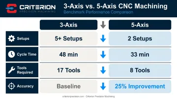
Those numbers reflect a real production scenario, not a theoretical model.
Why This Matters for Aerospace Specifically
Modern aerospace components (structural brackets, engine housings, actuator bodies) routinely have features on four or five faces, compound angles, and undercut geometry. On a 3-axis machine, producing these parts correctly can require five or more separate setups. Each refixturing event transfers the dimensional reference to a new datum, and each transfer accumulates error.
When tolerances on flight-critical parts are measured in ten-thousandths of an inch, that accumulation isn't acceptable. The downstream effects are concrete:
- Non-conformances caught at final inspection
- Rework cycles that consume lead time and drive up cost
- Scrapped parts when rework isn't feasible
- Missed delivery windows on programs with no schedule float
That error accumulation also shapes design decisions upstream. When engineers know a feature can't be held reliably with available equipment, they simplify it — the geometry gets adjusted to fit manufacturing constraints rather than performance requirements. Three-axis limitations have, for decades, defined the upper boundary of what aerospace parts could realistically look like.
How 5-Axis Machining Works: The Core Difference
The Two Additional Axes
A standard machining center moves in three linear directions: X (left/right), Y (front/back), and Z (up/down). 5-axis machines add two rotational axes (typically designated A, B, or C depending on which plane they rotate in) that allow the cutting tool or the workpiece to tilt and rotate during the cut.
The distinction that matters most in aerospace is 3+2 versus simultaneous 5-axis:
- 3+2 machining locks the rotational axes at a fixed compound angle, then performs standard 3-axis cutting from that position. It's efficient for structural features that can be reached from a fixed orientation and works well for many bracket and housing applications.
- Simultaneous 5-axis moves all five axes concurrently during cutting. The tool continuously adjusts its orientation relative to the surface it's following, maintaining consistent engagement throughout the toolpath.
Why Simultaneous Motion Matters for Aerospace
Turbine blade profiles, blended airfoil radii, and contoured engine casing surfaces cannot be produced to specification with 3+2 alone. These surfaces change curvature continuously — the tool must track that change in real time.
HEIDENHAIN's TNC 640 control documentation describes this precisely: the tool can be kept perpendicular to the workpiece surface throughout the motion, with the control calculating compensating linear-axis movements to keep the tool tip exactly on the programmed path as rotary axes turn.
Sandvik Coromant's profile milling guidance adds another dimension: tilting the spindle 10–15 degrees moves the cutting zone away from the tool center (where surface cutting speed approaches zero), dramatically improving cutting conditions on complex contours.
For flight hardware with aerodynamic surfaces or turbine blade profiles, simultaneous 5-axis motion isn't a premium option. It's the process requirement — the only method that consistently meets specification without secondary rework or dimensional deviation.
The Benefits of 5-Axis Machining for Aerospace Production
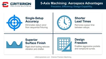
Single-Setup Accuracy
When all features are cut from a common datum without the part ever leaving the fixture, feature-to-feature relationships are as tight as the machine's positioning accuracy allows. There's no accumulated error from successive refixturing events — what the CAD model specifies is what the machine produces.
For aerospace programs, this translates directly to:
- Higher first-article acceptance rates
- Fewer non-conformances at final inspection
- More predictable delivery schedules on programs with zero schedule margin
Shorter Cycle Times and Lead Times
Consolidating five conventional setups into one 5-axis operation removes more than just setup time. It also eliminates queue time — the hours or days a batch of parts sits waiting for an open machine between operations. In high-mix aerospace environments with low lot sizes and tight schedules, that queue reduction is often as significant as the setup reduction.
Better Surface Finish on Critical Geometry
5-axis machining allows shorter, more rigid cutting tools. Because the spindle tilts toward the surface, tool overhang is minimized and vibration drops with it. The result is finer feature definition and consistent surface finish on sealing surfaces, bearing bores, and aerodynamic contours where roughness is a specification — not an afterthought.
That precision in execution directly expands what engineers can design.
Design Freedom
When aerospace engineers work with a machining partner that can reliably produce complex geometry, they design for performance rather than for manufacturability. Internal pockets, scalloped ribs, continuous compound curves, and aggressive weight-reduction features all become achievable.
5-axis capability is a key reason the lightweighting trend in commercial and defense aerospace has accelerated. The gains aren't purely from advanced materials — machining capability is doing real work too.
Better Material Utilization
Aerospace titanium and nickel superalloys are among the most expensive engineering materials in production. A 2023 peer-reviewed analysis found that conventional titanium manufacturing commonly produces buy-to-fly ratios of 8:1 to 15:1 — meaning 8 to 15 pounds of raw material purchased for every pound of finished part. Optimized 5-axis toolpaths approach the workpiece from better angles with more consistent chip loads, reducing unnecessary material removal and improving yield on expensive stock.
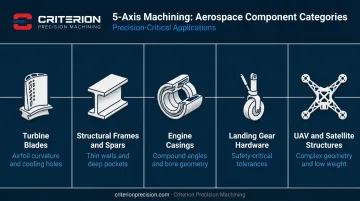
Aerospace Components Made Possible by 5-Axis Machining
| Component | Why 5-Axis Is Required |
|---|---|
| Turbine blades & vanes | Continuous airfoil curvature, root features, cooling hole angles |
| Structural frames & spars | Thin walls, deep pockets, multi-face features in 7000-series aluminum and titanium |
| Engine casings & housings | Compound-angle through-features, precise bore geometry, complex external contours |
| Landing gear & actuation hardware | High-strength materials, tight bearing surface tolerances, safety-critical dimensional accuracy |
| UAV & satellite structures | Complex geometry, low weight, rapid prototype-to-production transitions |
Turbine blades are the archetypal 5-axis part. Their airfoil profiles, leading and trailing edge geometry, and cooling hole orientations require the continuous tool-axis control that only simultaneous 5-axis provides. Any deviation from the designed profile changes both aerodynamic performance and thermal management — which is why Sandvik Coromant's aerospace blisk guidance specifically requires "a five-axis machine with good simultaneous dynamics" for cost-effective, high-quality production.
Structural frames and spars in 7075 and 7050 aluminum, or titanium, are designed with aggressive pocket removal to achieve maximum stiffness-to-weight ratio. The thin walls and deep cavities are far more reliably produced in a single 5-axis setup than through multiple conventional operations.
Engine casings must combine precise bore geometry, angled mounting faces, complex external profiles, and through-features at compound angles, all within a single part that operates under extreme thermal and mechanical load. A 2022 Chinese Journal of Aeronautics paper frames five-axis machine tool design explicitly around aero-engine casing requirements, citing accuracy and stiffness as primary drivers.
Machining Exotic Aerospace Materials with 5-Axis Technology
Titanium (Ti-6Al-4V)
Ti-6Al-4V is the dominant aerospace titanium alloy — NASA materials data indicates it accounts for approximately 60% of all titanium manufactured. Its strength-to-weight ratio and corrosion resistance make it ideal for airframes and engine structures. Its machinability makes it a challenge.
The problems are well-documented: thermal conductivity of just 6.7 W/m·K (roughly one-tenth of steel's conductivity), a specific cutting force of 1,400 N/mm², work hardening tendency, and chemical reactivity that promotes tool adhesion. Heat concentrates at the cutting zone rather than dissipating through chips, accelerating tool wear and creating dimensional instability across a production run.
5-axis machining addresses this by maintaining consistent cutter engagement angles throughout the toolpath. Consistent engagement produces consistent chip load: more uniform heat distribution and more predictable tool wear, both critical for holding tight tolerances across a batch of flight-critical parts. Criterion Precision Machining holds tolerances down to ±0.0002" on aerospace components, a specification that demands exactly this kind of process stability.
Nickel Superalloys (Inconel)
Inconel 718 is the standard material for turbine sections and exhaust components because it retains strength at temperatures that would cause most alloys to creep. That same thermal stability makes it extraordinarily difficult to machine.
Key machining challenges with Inconel 718:
- Thermal conductivity of only 11.4 W/m·K, concentrating heat at the cutting zone
- Specific cutting force reaching 2,900 N/mm² for aged nickel alloys
- Progressive work hardening that increases forces and accelerates tool wear as the cut proceeds
A 2024 Applied Sciences study on five-axis finish milling of an Inconel 718 blisk documented tool life of approximately eight blades per tool under optimized conditions. Simultaneous 5-axis toolpath strategies that maintain consistent engagement are what make those conditions achievable — fixed-axis approaches that allow engagement to vary produce worse tool life and less dimensional consistency.
Aerospace Aluminum Alloys
7050 and 7075 aluminum machine more freely than titanium or Inconel, but 5-axis capability matters here too — for different reasons. High-speed 5-axis machining of aluminum structural components achieves the aggressive pocket removal and complex contoured geometry that define lightweight airframe parts. Metal removal rates on aluminum structural components at 5-axis can be significantly higher than conventional approaches, which matters when cycle time drives program economics.
Inspection Closes the Loop
Machining an exotic alloy to specification is half the challenge. Verifying it is the other half. Criterion's inspection infrastructure covers both:
- Global Advantage CMM with PC-DMIS software — complex 3D geometric verification at aerospace tolerance levels
- OASIS Optical Automatic Smart Inspection System — rapid multi-dimension measurement for in-process and final checks
- Keyence measuring systems — up to 99 dimensions simultaneously for high-throughput production runs
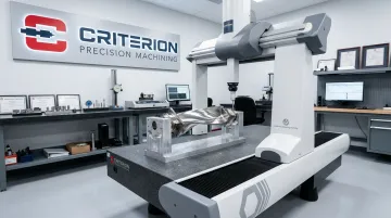
Together, these systems confirm part conformance at every stage, supporting first-article approval and on-time delivery of documented, traceable components.
What to Look For in an Aerospace 5-Axis Machining Partner
Certifications and Compliance Infrastructure
Certifications in aerospace aren't marketing credentials. They're evidence that a supplier's quality system, documentation practices, and process controls meet the industry's minimum standards for flight-critical work.
What matters:
- AS9100D — The aerospace-specific quality management standard covering design, production, and delivery of aviation, space, and defense products; required by most prime contractors and OEMs
- ISO 9001:2015 — Baseline quality management system requirements covering process control, document management, and continual improvement
- ITAR registration — Legally required under DDTC regulations for any supplier manufacturing, exporting, or furnishing services related to defense articles
- Full material traceability — Raw material certifications with actual chemical and physical properties, lot traceability to the melt, and FAI documentation per SAE AS9102
Criterion Precision Machining holds AS9100D and ISO 9001:2015 certifications, is ITAR and FDA registered, and maintains tight tolerances down to ±0.0002" — the compliance baseline a "no failure" aerospace program requires.
Proven Experience with Aerospace Alloys
Owning a 5-axis machining center doesn't equal process knowledge. A supplier with limited production history on Ti-6Al-4V or Inconel 718 will struggle to hold tolerances and manage tool life through a production run.
Ask prospective suppliers:
- What aerospace alloys do you machine in regular production?
- What are your typical first-article acceptance rates on new programs?
- How do you manage tool life and cutting parameters on titanium or Inconel across a batch?
Integrated Quality Systems and Traceability
An aerospace machining partner should be able to document every step from incoming raw material through final inspection. Criterion's ProShop ERP platform delivers real-time production visibility, lot traceability, and a documentation framework that supports customer audits and regulatory reviews.
Full documentation packages — including FAIRs, Certificates of Conformance, and material traceability records — are available at no additional charge. That's a practical indicator that traceability is built into the process, not assembled after the fact.
In-house secondary operations are equally relevant to traceability. Criterion's capabilities include wire EDM for complex features, fiber laser marking for ITAR-compliant part serialization, and mass finishing for surface condition requirements — reducing the supply chain hand-offs that introduce documentation gaps on multi-operation aerospace programs.
Frequently Asked Questions
What aerospace components are most commonly produced using 5-axis machining?
Turbine blades, structural brackets and spars, engine casings, landing gear components, and UAV/satellite structures are the most common. Any part requiring compound angles, deep pockets, or continuously contoured surfaces is a strong candidate for 5-axis production.
How does 5-axis machining improve dimensional accuracy on flight-critical parts?
Single-setup machining holds all features to one common datum, eliminating the dimensional error that accumulates each time a part is repositioned. This removes tolerance stack-up and produces significantly higher first-article acceptance rates on complex parts.
What is the difference between 3+2 and simultaneous 5-axis machining in aerospace applications?
3+2 locks the part at a compound angle for standard 3-axis cutting, which handles many structural features well. Simultaneous 5-axis moves all axes concurrently during cutting — essential for turbine blade profiles, blended radii, and contoured surfaces where both surface finish and tolerance are critical.
Why are titanium and Inconel so difficult to machine, and how does 5-axis help?
Both materials generate high cutting forces and heat with poor thermal dissipation, causing accelerated tool wear and dimensional instability. Simultaneous 5-axis motion maintains consistent cutter engagement, distributing heat and load more evenly for longer tool life and tighter tolerances.
What certifications should an aerospace precision machining supplier hold?
AS9100 is the aerospace-specific quality management standard and the primary cert to require. ISO 9001 establishes the baseline; ITAR registration is legally required for defense and space programs. Suppliers should also provide full traceability documentation — raw material certifications, FAIRs, and Certificates of Conformance — with every shipment.
How does 5-axis machining support weight reduction in aerospace design?
5-axis capability allows engineers to specify aggressive internal pockets, scalloped ribs, and optimized structural contours that remove mass without sacrificing stiffness. These geometries are only reliably manufacturable with 5-axis access — conventional machining forces design compromises that leave weight on the airframe.