Introduction
Many optical engineers struggle with a common challenge: mechanical positioning errors that compromise beam quality, reduce coupling efficiency, and degrade system reliability. Even microscopic deviations—just a few microns—can cause laser beams to drift out of focus, fiber optic connections to suffer signal loss, or imaging systems to introduce unacceptable aberrations.
Sub-micron tolerances (typically 0.1 to 5 microns, or less than 0.0002") represent the threshold where mechanical precision directly determines optical performance. Research shows that a lateral misalignment of just 1 micron in single-mode fiber coupling results in approximately 4.2% signal loss, while angular misalignment of 1 micron over 10mm translates to roughly 20 arc-seconds of beam deviation.
This article covers how sub-micron tolerances function as design constraints, what drives their achievability, and how to specify and validate them so your system performs as intended.
Key Takeaways
- Sub-micron tolerances (0.1–5 microns) are critical for optical components including lens mounts, mirror substrates, and positioning stages
- Tighter tolerances improve beam collimation and coupling efficiency — but costs rise exponentially as specs tighten
- What's achievable depends on machining method, material thermal stability, and environmental controls
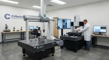
- Verification requires CMMs, optical interferometry, and metrology tools with at least 10:1 measurement capability
What Sub-Micron Tolerances Represent in Optical Alignment Machining
Sub-micron tolerances refer to dimensional accuracy requirements below 1 micron (0.001 mm), typically ranging from 0.1 to 5 microns depending on application criticality. These specifications govern mechanical positioning accuracy, surface flatness, parallelism, and perpendicularity of optical mounting surfaces — the same surfaces that determine whether a finished system hits spec or misses it.
Fixed at the Machine: Why Tolerances Are Design Constraints
These tolerances function primarily as design constraints and manufacturing specifications rather than dynamic alignment adjustments. Once a lens mount is machined to a specified tolerance, that mechanical accuracy becomes fixed. Active alignment techniques may compensate during assembly, but the mechanical foundation sets the baseline performance envelope.
That baseline matters because mechanical tolerances translate directly into optical performance metrics — often in ways that aren't recoverable downstream:
- Wavefront error: A surface deviation of 0.1 microns creates a 0.2 micron wavefront error in reflection (approximately λ/3 at visible wavelengths), enough to degrade image quality in demanding imaging applications
- Beam pointing stability: Lateral shifts in lens positioning translate directly to beam pointing errors that compromise coupling efficiency
- Focal plane positioning: Axial positioning errors shift the focal plane, reducing modulation transfer function in imaging systems
Precision Spectrum Context
Optical alignment machining occupies a specific band on the broader precision spectrum:
- Standard precision machining: ±25 microns (±0.001")
- Optical alignment machining: 0.5–5 microns (±0.0002")
- Ultra-precision machining: <0.1 micron (100 nanometers)
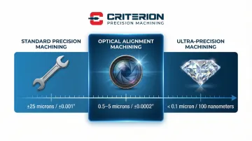
This places optical alignment in a demanding middle ground — tighter than general precision work but not requiring the extreme capabilities of nanometer-scale diamond turning. Reaching it consistently requires controlled environments, appropriate metrology, and machining processes that account for thermal growth and tool deflection — capabilities that go well beyond a standard CNC setup.
Factors That Influence Tolerance Achievement in Optical Alignment Components
Achieving sub-micron tolerances requires far more than standard machining practices. Three critical factor categories determine whether a manufacturer can consistently deliver optical-grade components.
Advanced Manufacturing Processes
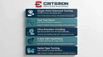
Each technique below targets a specific precision challenge — no single process covers every optical alignment requirement:
- Single-point diamond turning (SPDT): Achieves ±0.001 micron dimensional tolerances with surface roughness (Ra) below 1 nanometer — the standard for precision optical surfaces
- Fast Tool Servo (FTS): Generates freeform optical surfaces with sub-micron form accuracy, critical for correcting aberrations in complex optical assemblies
- Ultra-precision grinding: Applied to hard materials like glass and ceramics where diamond turning isn't viable; capable of sub-micron form error
- 5-axis CNC machining: Handles complex geometries in a single setup, eliminating the positioning errors introduced by repositioning between operations
- Swiss-type turning: Holds sub-5 micron tolerances on small-diameter components down to 0.010" — essential for miniaturized optical housings and shafts
Criterion Precision Machining combines Swiss turning, CNC milling, and CNC turning to achieve tolerances as tight as ±0.0002" (approximately 5 microns) for optical alignment components. 5-axis systems add the flexibility needed to maintain tight concentricity on complex bores and cylindrical features in a single operation.
Material Selection Impact
Process capability only gets you so far. The material itself — its thermal behavior, machinability, and dimensional stability — determines whether tolerances hold once the part leaves the machine.
Thermal Expansion Considerations
Material thermal stability is critical at the sub-micron scale. For titanium alloys like Ti-6Al-4V, a temperature change of just 1°C causes expansion of approximately 8.6 nanometers per millimeter of length. In a 100mm assembly, a 0.5°C shift results in over 0.4 microns of drift—consuming nearly half of a ±1 micron tolerance budget.
Machinability Characteristics
- Aluminum alloys: Excellent machinability with CTE of ~23 ppm/°C; a 100mm component expands 2.3 microns per 1°C
- Titanium (Ti-6Al-4V): Machinability rated at 22% of steel; requires low cutting speeds but offers superior strength-to-weight ratio for aerospace optics
- Stainless steels: Good dimensional stability but challenging to machine without work hardening
- PEEK and engineered plastics: Enable non-conductive or non-reflective surfaces when required
For applications requiring extreme thermal stability, Invar or Super Invar alloys are often necessary despite their machining challenges.
Environmental Control Requirements
Even with the right process and material, the shop environment itself can introduce errors that invalidate sub-micron work. Controls must govern the entire production and measurement cycle:
- Temperature stability: Metrology labs and ultra-precision machining centers typically require 20°C ±0.1°C or better to negate thermal expansion effects
- Vibration isolation: External vibrations must be isolated; nanopositioning stages specify noise floors in the nanometer range to prevent positional jitter
- Humidity management: Moisture can affect both material dimensions and measurement accuracy
- Contamination control: Particulate contamination can prevent proper component seating, creating offsets exceeding 1 micron
Range of Sub-Micron Tolerances in Optical Alignment Applications
Tolerance requirements vary significantly based on optical system type, wavelength, numerical aperture, and performance criticality. These ranges give engineers a practical baseline for specifying tolerances that meet performance requirements without over-engineering components.
Typical Tolerance Ranges by Application
Laser Alignment Systems (0.5-2 microns)
High-end laser alignment stages driven by piezo actuators specify bi-directional repeatability of <1 micron, with top-tier models achieving 30-80 nanometers. Closed-loop piezo stages offer resolution down to 0.2 nanometers, allowing active alignment compensation well within sub-micron limits. Surface detection and alignment must be reproducible to <1 micron to ensure focal spots interact correctly with targets.
Fiber Optic Coupling (0.2-1 micron)
Single-mode fibers present the tightest tolerance requirements. With mode field diameters of approximately 9-10 microns at telecom wavelengths, lateral offset must be controlled to <1 micron to keep coupling loss below 0.2 dB. Research indicates that lateral misalignment of ±0.8 microns can result in a 1 dB penalty, while some sub-wavelength grating couplers require tolerances as tight as 20 nanometers.
Multimode fibers, with core diameters of 50-62.5 microns, allow looser tolerances of ±5-10 microns for comparable efficiency losses.
Photonics Packaging (0.1-0.5 microns)
Edge couplers for chip-to-fiber connections are highly sensitive to misalignment. Automated alignment systems for photonics packaging routinely operate with <50 nanometer position tolerances to optimize coupling efficiency. Mode matching between a fiber and an on-chip waveguide — where both components measure in single-digit microns — leaves no margin for error.
Microscopy Stages (1-5 microns)
Precision microscopy stages, especially those used in super-resolution imaging, typically specify accuracy in the range of 1.4-1.6 microns plus a proportional component (L/200 to L/250), with repeatability significantly better at sub-micron levels. These specifications support nanometer-scale imaging requirements while acknowledging that longer travel distances accumulate proportional errors.
Tolerance Stack-Up and Design Margins
Individual component tolerances accumulate in multi-part assemblies, making tolerance analysis critical for system-level performance. In passive fiber alignment schemes, the combined stack-up of ferrule, bore, and sleeve dimensions can consume the entire alignment budget. High-performance single-mode connections typically require active alignment — light-through measurement — to compensate.
Design Margin Philosophy
Optical systems are typically designed with a 2-3× safety margin beyond minimum tolerance requirements to account for:
- Assembly variation and kinematic coupling repeatability
- Thermal drift during operation
- Component aging and mechanical wear
- Manufacturing process capability variations
This conservative approach ensures that systems maintain performance specifications throughout their operational lifetime despite inevitable degradation factors.
Key Technical Properties Affected by Sub-Micron Tolerances
Sub-micron tolerances directly shape optical performance across three interdependent parameters: axis alignment, surface form, and coupling efficiency. Each has quantifiable consequences — and each compounds the others.
Optical Axis Alignment and Beam Pointing Stability
Angular misalignment translates to positional error over distance according to the relationship: s = L × θ, where s is lateral shift, L is lever arm length, and θ is angular error.
One arc-second equals approximately 4.85 microradians. Over a 100mm lever arm, a 10 arc-second misalignment produces a positional shift of approximately 4.85 microns — a critical relationship when specifying parallelism for optical windows or mounting surfaces.
For lens positioning, angular misalignment of 1 micron over 10mm translates to approximately 20 arc-seconds of beam deviation. That directly affects coupling efficiency in fiber optic systems and beam delivery accuracy in laser manufacturing.
Kinematic mounts must provide consistent repositioning to maintain long-term beam pointing stability. High-precision mounts specify repeatability of <1 micron. That ensures optical elements return to the same position after removal and reinstallation — essential for modular systems requiring field serviceability.
Surface Flatness and Parallelism
Surface flatness deviations cause wavefront distortion measured in fractions of a wavelength. Optical surfaces are typically specified at a test wavelength of 633nm:
- λ/10 flatness: Approximately 63 nanometers (0.063 microns) peak-to-valley deviation, considered high quality for most applications
- λ/20 flatness: Approximately 31 nanometers (0.031 microns), required for demanding interferometric or imaging applications
A mirror with λ/10 surface irregularity contributes λ/5 to wavefront error — light reflects from the surface, doubling the optical path difference. Surface form tolerances therefore set a hard ceiling on transmitted or reflected wavefront quality.
Parallelism matters equally for windows and beamsplitter substrates. High-precision applications typically require <30 arc-seconds; standard precision may allow 1–5 arc-minutes depending on beam diameter and application sensitivity.
Coupling Efficiency and System Throughput
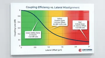
The relationship between positional tolerance and coupling efficiency is exponential, not linear. For single-mode fiber coupling, efficiency drops sharply with lateral offset:
- 1 micron lateral misalignment: Reduces fiber coupling efficiency by approximately 4.2% (0.2 dB loss)
- 2 micron lateral offset: Increases loss to >0.5 dB
- Offset within ±1 micron: Keeps loss negligible (<0.2 dB)
These losses compound across a full optical train. A 10-element system with 1% loss per interface delivers only 90.4% total transmission (0.99¹⁰) — nearly 10% total loss from errors that appear negligible in isolation. Each additional element narrows the margin further.
How Sub-Micron Tolerances Are Specified, Measured, and Validated
Proper specification requires understanding both GD&T (Geometric Dimensioning and Tolerancing) standards and optical metrology capabilities. The gap between specification and verification capability often determines whether components actually meet requirements.
Specification Methods
GD&T Standards (ASME Y14.5-2018)
Engineering drawings use GD&T callouts to define tolerances unambiguously:
- Position locates features relative to datums with no ambiguity
- Runout controls surface variation during rotation
- Perpendicularity defines angular relationships to reference surfaces
- Parallelism governs how closely surfaces align to a reference plane
Proper datum selection (optical axis vs. mechanical housing) is critical to avoid "methods divergence" where measurement results vary based on reference frame. The 2018 revision clarifies that "elements of a surface include surface texture and flaws," vital for optical interfaces where surface quality affects performance.
Optical Surface Specifications
Beyond dimensional tolerances, optical components require:
- Scratch-dig ratings such as 40-20 define the maximum allowable surface defects
- Ra values below 10 nanometers for surface roughness on optical faces
- Standardized mounting interfaces to ensure cross-system compatibility
Measurement and Verification Approaches
Coordinate Measuring Machines (CMM)
High-end CMMs offer resolution down to 0.1 microns or better. Systems operating at 20±0.1°C support sub-micron measurements with motorized probe heads and PC-DMIS software for complex 3D dimensional inspection.
Optical CMMs combine optical and tactile sensors, reaching accuracy around 1.4–1.9 microns for complex optical parts. Non-contact measurement protects delicate surfaces from damage during inspection.
Optical Interferometry
For surface form and flatness, interferometry represents the gold standard. Systems measure surface deviations with sub-nanometer vertical resolution, far exceeding tactile CMM capabilities for flatness verification. NIST calibration of optical flats involves uncertainty budgets accounting for reference flat errors, thermal effects, and deformation, often totaling only a few nanometers.
Laser Autocollimation
Angular measurements use laser autocollimation techniques to verify parallelism, perpendicularity, and angular positioning with arc-second resolution. This non-contact method provides rapid angular verification without the time-intensive scanning required by CMM or interferometry.
Measurement Capability Requirements
The 10:1 Rule and Uncertainty Budgets
ISO 17450 and industry best practices recommend a measurement capability ratio of 10:1 — a 1 micron tolerance requires a gauge capable of 0.1 micron resolution and uncertainty. Standard CMMs often lack this capability for sub-micron tolerances, making interferometry or specialized nano-CMMs necessary.
The ISO GUM (Guide to the Expression of Uncertainty in Measurement) adds another layer: when expanded uncertainty is significant relative to tolerance, the conformance zone must be narrowed through guard-banding (narrowing the acceptable tolerance zone) to ensure compliance with high confidence.
Traceability Standards
Companies with ISO 13485 and ISO 9001 certification typically maintain calibrated metrology traceable to national standards bodies like NIST or NPL. This traceability chain is mandatory for regulatory audits in medical device and aerospace applications.
Criterion Precision Machining holds both ISO 13485:2016 and ISO 9001:2015 certifications, with its metrology suite calibrated to those same traceable standards. Equipment includes a Global Advantage CMM with sub-micron resolution, OASIS optical inspection systems, and Keyence measuring systems that can capture up to 99 dimensions simultaneously.
Implications of Operating Outside Specified Tolerances
Exceeding alignment tolerances triggers multiple failure mechanisms that degrade performance and potentially compromise system functionality entirely.
Performance Degradation Mechanisms
Insertion loss compounds quickly in fiber optic systems. A shift from 1 micron to 2 micron offset can double or triple insertion loss in dB terms, directly cutting into link budget and system range.
Beam clipping from misaligned apertures introduces diffraction effects that degrade beam quality (M² factor) and reduce usable power. In laser manufacturing, clipped beams create non-uniform intensity distributions that compromise processing quality.
Lens misalignment introduces primary aberrations — coma and astigmatism chief among them. These degrade the Modulation Transfer Function (MTF), reducing image contrast and resolution. Even 5-10 micron decentrations in high-numerical-aperture objectives introduce visible aberrations.
Accelerated Failure Modes
These immediate performance losses don't exist in isolation. Over time, out-of-tolerance conditions accelerate physical degradation across three interconnected mechanisms:
- Thermal stress: CTE mismatches left unaddressed in tolerance design cause stress buildup during thermal cycling — leading to optical surface deformation or outright cracking of optics and bond lines. Space applications face this most acutely given the extreme thermal environments involved.
- Mechanical wear: Misaligned moving stages produce uneven bearing loads, increasing friction and eroding positioning repeatability with each cycle.
- Coating damage: Concentrated beam intensity from misalignment exceeds coating damage thresholds, producing localized failure that worsens with continued operation.
Compliance and Warranty Implications
Medical device manufacturers operating under FDA QMSR (which incorporates ISO 13485) must validate that products meet specified requirements. Alignment tolerance failures produce non-conforming product — and where laser delivery accuracy affects patient safety, the consequences extend to recalls and redesigns.
Aerospace programs face equally rigid exposure. NASA and military standards such as MIL-STD-1540 require optical payloads to survive launch vibration and thermal vacuum environments without exceeding critical alignment thresholds. Out-of-tolerance components fail qualification testing and void certifications — a costly outcome at any program stage.
Common Misinterpretations of Sub-Micron Tolerances in Practice
Several misconceptions about sub-micron tolerances lead to over-specification, inadequate verification, or unrealistic expectations.
Tighter Tolerances Don't Always Improve Performance
Manufacturing costs increase exponentially as tolerances tighten. Moving from "Precision" (±25 microns) to "High Precision" (±6 microns) typically doubles costs — and further tightening to sub-micron levels carries even steeper multipliers due to yield loss and metrology costs.
Beyond application-critical thresholds, performance gains diminish while costs keep climbing. A system requiring 2-micron tolerance gains nothing from specifying 0.5 microns except higher component costs and longer lead times.
Measurement Uncertainty Is Not Optional
A common error is specifying tolerances without considering measurement uncertainty. A 1-micron tolerance requires measurement capability of at least 0.1–0.2 microns per ISO standards. If your supplier's CMM has 0.5-micron uncertainty, they cannot reliably verify 1-micron tolerances.
Measurement uncertainty and measurement error are not the same thing. Uncertainty quantifies the inherent doubt in any result — even a flawless measurement carries it. For reliable conformance, uncertainty must stay below 1/3 of the specified tolerance. Two practical rules follow from this:
- Confirm your supplier's CMM uncertainty before specifying sub-micron tolerances
- Require documented uncertainty budgets, not just pass/fail inspection reports
Without this, tighter tolerances on paper offer no real quality assurance.
Confusing Different Tolerance Types
Three tolerance categories apply in optical machining, and they behave differently:
- Positional tolerances define where a feature sits — for example, a hole center within 1 micron of true position
- Geometric tolerances define feature shape, such as cylindricity or flatness held within 0.5 microns
- Surface finish defines surface texture, such as roughness Ra below 10 nanometers
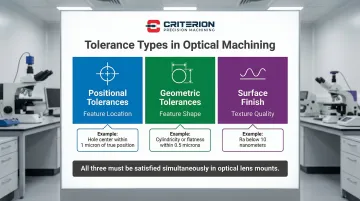
In optical applications, these are often coupled. A lens mount must satisfy all three: correct position (centration), correct geometry (bore roundness), and appropriate finish to avoid optic damage. Over-specifying one while ignoring another is a common and costly mistake.
The same logic extends to assemblies. Individual components held to 1-micron tolerances can accumulate 3–5 microns of total error in a multi-part stack unless tolerance analysis is built into the design from the start.
Conclusion
Sub-micron tolerances are governing parameters for optical alignment system performance, not merely manufacturing specifications. They directly determine coupling efficiency, beam quality, and long-term stability in photonics, imaging, laser, and fiber optic systems. A lateral misalignment of just 1 micron can reduce fiber coupling efficiency by 4–10%, while surface flatness deviations of 0.1 microns introduce wavefront errors that degrade image quality.
Achieving these tolerances demands a specific combination of capabilities:
- Machining processes: Diamond turning, precision grinding, 5-axis CNC, and Swiss turning with advanced tooling
- Environmental controls: Temperature stability of ±0.1°C, vibration isolation, and contamination management
- Material selection: Accounting for thermal expansion coefficients and machinability at sub-micron scales
- Metrology: Systems with 10× better capability than the tolerances being measured—interferometry, nano-CMMs, and calibrated inspection traceable to national standards
Those metrology and process requirements translate directly into what you need from a manufacturing partner. Suppliers must demonstrate validated metrology, documented environmental controls, and quality systems (ISO 13485, ISO 9001) alongside raw machining capability.
The difference between a 2 micron and 5 micron tolerance capability determines whether your optical system meets performance requirements or requires costly redesign and rework.
Frequently Asked Questions
What are reasonable tolerances for optical alignment machining?
Reasonable tolerances depend on application requirements. General optical mounts typically require ±5 microns, precision laser alignment systems need ±1-2 microns, and fiber optic coupling applications demand ±0.5 microns or tighter. Tighter tolerances require specialized capabilities including diamond turning or ultra-precision grinding, environmental controls, and advanced metrology. Specify tolerances based on optical performance requirements, not arbitrary precision targets.
Is 0.005 in (5 thou) a tight tolerance for optical alignment machining?
No, 0.005" equals approximately 127 microns, which is relatively loose for optical alignment applications where sub-5 micron tolerances are common. This tolerance may be adequate for lower-precision mounting structures or housing exteriors, but critical optical interfaces (lens bores, mounting surfaces, kinematic features) typically require tolerances 25-100× tighter. For reference, precision optical alignment commonly specifies ±0.0002" (approximately 5 microns).
What are typical tolerances for micromachining in optical applications?
Optical micromachining typically achieves 0.5-2 micron tolerances for critical features using advanced CNC processes, Swiss turning, and precision grinding. Ultra-precision diamond turning can reach sub-0.1 micron (sub-100 nanometer) tolerances for specialized applications like freeform optics or mirror substrates. Achievable tolerance varies with feature size, material properties, and process selection.
What is precision alignment in optical alignment machining?
Precision alignment is the process of achieving and maintaining optical component positioning within specified tolerances, combining mechanical fabrication accuracy with active or passive alignment techniques. It covers both manufactured interface precision (sub-micron bore tolerances, surface flatness, parallelism) and assembly procedures that ensure components hold their designed relationships throughout the system's service life.
What is the most precise alignment method for optical components?
Active alignment with real-time optical feedback provides the highest precision (sub-0.1 micron), using coupling efficiency and beam quality to guide positioning during assembly. Kinematic mounting achieves 0.5-2 micron repeatability; standard mechanical fixturing provides 2-5 microns. The right method balances precision requirements against cost and assembly complexity.
What are the common types of misalignment in optical systems?
Six primary misalignment types affect optical systems:
- Lateral displacement — X-Y positioning errors causing beam offset
- Angular misalignment — tip-tilt causing beam pointing errors
- Axial displacement — focus errors shifting the focal plane
- Rotational misalignment — clocking errors affecting polarization or image orientation
- Decentration — lens center offset from optical axis
- Tilt — lens surface not perpendicular to optical axis
Lateral and angular errors typically dominate coupling efficiency losses, while axial errors primarily affect focus and image quality.