Introduction
In aerospace, medical device, defense, and photonics, bore location errors measured in ten-thousandths of an inch can cascade into assembly failures and costly nonconformances. The FDA has recorded recalls of dental implants where nonconforming dimensional features prevented proper driver engagement. NASA's shop standards explicitly reference jig bore work for four- and five-place decimal machine-setting dimensions.
Boeing's supplier quality requirements charge up to $1,000 per nonconformance document. That figure doesn't include rework, schedule impacts, or downstream consequences.
This guide covers everything engineers and procurement teams need to know about tight tolerance jig bore machining: what it is, how the process works step by step, which factors determine whether your bore hits tolerance or misses it, how bores are inspected, and what to look for in a machining partner qualified to hold these dimensions reliably.
Key Takeaways
- Jig boring achieves hole location accuracy within 1–5 microns and diameter tolerances at ±.0002" or tighter
- Machine thermal stability, spindle runout, tool rigidity, and workholding each independently affect bore accuracy
- CMM measurement with full GD&T reporting is the correct verification method for tight-tolerance bores
- Aerospace, defense, medical device, and photonics are the primary industries where jig bore tolerances are non-negotiable
- Supplier qualifications must include certifications, in-house metrology, and documented inspection records
What Is Tight Tolerance Jig Bore Machining?
Jig bore machining is a precision hole-making and hole-correcting process performed on a machine built specifically for extreme positional and dimensional accuracy. Boring operations run on many machine types. What separates jig boring is the machine's architecture — the feedback systems, thermal stability, and slideways engineered to hold position at sub-micron levels.
According to Mitsui Seiki's published jig boring guidance, high-end jig boring machines use 0.0001 mm resolution linear-scale feedback and achieve positioning tolerances of 1 micron. The Mitsui Seiki J6CN carries an official X/Y/Z positioning accuracy specification of ±0.001 mm (±0.00004").
Those specs translate directly into what shops can hold on the floor. In practice, tight tolerance jig bore machining delivers:
- Hole location accuracy: within 1–5 microns relative to datum
- Diameter tolerance: ±.0002" or tighter in demanding applications
- Geometric accuracy: less than 5 microns in roundness, perpendicularity, and straightness for mold-base class work
Jig Boring vs. Standard CNC Boring vs. Reaming
These three processes get grouped together in conversation, but each addresses a different problem:
| Process | Location Correction | Diameter Tolerance | Best Application |
|---|---|---|---|
| Jig Boring | Yes — primary strength | ±.0002" or tighter | When both position AND diameter must hit extreme tolerances simultaneously |
| Finish Boring (CNC) | Limited | IT6–IT8 class | Close-tolerance finishing when location is already established |
| Reaming | No | IT6 class, ~Ra 0.25 | Diameter and finish only; cannot correct hole position |
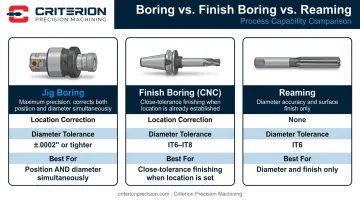
Reaming is a diameter and finish operation. Sandvik Coromant confirms that reaming provides close dimensional tolerance at high penetration rates — but it follows the existing hole location. If that location is wrong, reaming locks in the error.
Move to jig boring when:
- Positional tolerances are tighter than ±.0005"
- Multiple bores must be precisely spaced or concentric relative to each other
- The component is mission-critical and cannot tolerate rework after machining
Vertical vs. Horizontal Jig Boring
The machine orientation affects which geometries and workpiece sizes are practical:
- Vertical jig borers — spindle vertical, table moves in X/Y; work strokes typically up to 40" × 60"; use one V-way and one flat way on the table axis; best for flat-surface bores, mold bases, fixture plates, and aerospace structural parts
- Horizontal jig borers — spindle horizontal; double V-ways in all slideways; better suited for side-face bores, large or odd-shaped workpieces, and setups where gravity assists chip evacuation
Modern CNC versions of both configurations can incorporate 4th and 5th axis capability, expanding the range of features addressable in a single setup.
The Jig Bore Machining Process: Step by Step
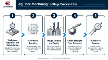
Step 1 — Workpiece Alignment and Datum Setup
Before any cutting begins, the part must be precisely indicated to establish true reference datums. Machinists use dial test indicators and precision squares to confirm alignment within microns. Any angular or positional error in the setup translates directly into bore location error: there's no downstream correction for a misaligned datum.
Step 2 — Coordinate Location
With datums established, the spindle is positioned to the exact bore center using the machine's precision coordinate system (optical scales, laser feedback, or precision lead screws) referencing those datums.
This is the step that separates jig boring from other processes. The machine's positioning accuracy must exceed the required bore location tolerance, not merely match it.
Step 3 — Rough Drilling and Rough Boring
The pre-machining sequence removes bulk material and corrects drill wander:
- Pilot drill — undersized hole establishes the bore centerline
- Rough bore — removes the majority of material and improves straightness and roundness
- Controlled stock allowance — typically 0.10–0.20 mm per side left for the finish pass, depending on bore diameter and L:D ratio
BIG KAISER's cutting data confirms stock allowances of 0.10–0.20 mm on diameter for finish boring steel with carbide tools, with feeds ranging from 0.04–0.10 mm/rev depending on nose radius and L:D ratio.
Step 4 — Finish Boring to Final Tolerance
With rough stock removed and the bore centerline confirmed, the finish pass removes the last few thousandths using conservative parameters:
- Fine-adjustable boring head set via micrometer or digital offset (Sandvik's fine boring heads adjust by increments of 0.002 mm / 0.00008")
- Low feed rate, minimal depth of cut, consistent RPM
- Thermal stabilization of machine and workpiece confirmed before this pass
Cutting parameters shift with L:D ratio. Longer bars require reduced feeds and tighter stock allowances to prevent deflection-induced size errors.
Step 5 — In-Process Gauging
Tight tolerance jig bore work is not measure-once-at-the-end work. Because each pass affects the next, measurements between passes confirm diameter, roundness, and position before the part leaves the machine. Bore gauges, air gauges (suitable from IT2 through IT7 per Marposs specifications), or CMM probing serve this function depending on the tolerance band and feature geometry.
Offset adjustments are made from measured results, not from nominal tool settings. The tool's theoretical position and the actual bore position diverge — measurement closes that gap.
Key Factors That Determine Bore Accuracy
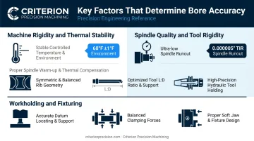
Machine Rigidity and Thermal Stability
Jig boring machines are built with heavy, symmetrical castings specifically to resist thermal growth and structural deflection. At tolerances measured in microns, temperature is not a background concern—it's an active variable.
ISO 1:2022 establishes 20°C (68°F) as the standard reference temperature for dimensional measurement. Mitutoyo's calibration lab documentation shows that holding a 300 mm micrometer with a bare hand for 20 minutes can cause approximately 14 microns of thermal expansion—more than twice the positional tolerance on many jig-bored features.
High-precision shops address this through:
- Temperature-controlled environments (typically 68°F ±1°F)
- Spindle warm-up cycles before critical work
- Symmetric machine casting designs that respond uniformly to temperature changes, minimizing differential growth
Thermal stability is only part of the equation — how the machine moves matters just as much. Vertical jig borers use one V-way (the precision guide) and one flat way (the load bearer). Horizontal machines use double V-ways in all axes. Precision lubrication with needle roller bearings delivers sub-micron positioning repeatability with minimal stick-slip.
Spindle Quality and Tool Rigidity
Spindle runout is the primary driver of bore roundness and concentricity. Historical Moore No. 3 Jig Borer specifications document spindle runout of 0.000005" TIR—a benchmark that illustrates what purpose-built jig boring spindles achieve compared to general-purpose machining centers.
Boring bar selection comes down to three variables:
- Bar diameter: Maximize for the bore size — larger diameter directly reduces deflection
- L:D ratio: Keep as low as geometry allows. Sandvik recommends a maximum 4× DMM for steel bars and 6× DMM for carbide before damped bars are required
- Tool holding: Hydraulic or shrink-fit holders are preferred over collets — collets can amplify residual spindle runout at tight tolerances
Workholding and Fixturing
Non-uniform clamping forces elastically distort the workpiece. A bore that measures in-tolerance under clamp load can spring out of tolerance once the part is released—a failure mode that passes inspection and shows up at assembly.
Proper fixturing principles for tight-tolerance bore work:
- Support the part at its natural datum surfaces
- Apply clamping forces symmetrically
- Use soft jaws or precision-ground fixtures for irregular geometries common in aerospace and medical components
Industries and Applications Requiring Tight Tolerance Jig Bore Machining
Aerospace and Defense
Aerospace and defense assemblies routinely require jig bore work for components where hole-to-hole position tolerances and concentricity cannot be achieved by other means. Common applications include:
- Structural alignment bores
- Actuator housings
- Gearbox and transmission cases
- Landing gear components
- Weapon system receiver components
NASA's shop standards explicitly call out jig bore work for precise machining applications. Criterion's ISO 9001 certification and ITAR registration qualify them for these applications — their customer history includes NASA and FLIR.
Medical Device and Photonics
Medical device and photonics components demand equal precision through different failure modes. Surgical instrument components, orthopedic implant housings, and endoscopic device parts require tight bore concentricity and smooth internal finishes that affect fit, function, and sterilizability. In photonics, alignment tolerances are often in the micron or sub-micron range — bore misalignment doesn't just cause dimensional nonconformance, it degrades optical path accuracy measurably.
Criterion's ISO 13485 certification covers medical device bore machining at tolerances down to ±.0002". Their customer list includes Smith & Nephew, Riverpoint Medical, and Corning.
Tooling, Mold Bases, and Fixture Plates
Beyond end-use components, tooling and fixture applications rely on jig boring as the standard finishing process for guide pin bushing bores, dowel pin holes, and cavity alignment features. Mitsui Seiki confirms that mold-base bores require less than 5 microns in location, roundness, perpendicularity, and straightness — bore-to-bore spacing held to a few microns determines whether a mold produces consistent parts or cumulative reject rates over thousands of cycles.
Inspection and Verification of Tight Tolerance Bores
Dimensional Verification Methods
The inspection tool must be capable of resolving the tolerance band. For tight-tolerance jig-bored features, that means more than a telescoping gauge:
- Bore micrometers — production checks; fast but operator-dependent
- Air gauges — fast, accurate diameter measurement; Marposs M1 air gauges cover IT2 through IT7 and surface finish to Ra 0.8 µm
- CMM with probe systems — full geometric characterization including diameter, roundness, cylindricity, true position, and perpendicularity in a single setup
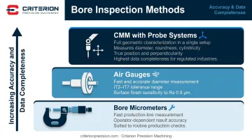
Criterion's quality lab operates a Global Advantage CMM with PC-DMIS software, capable of measuring and reporting all critical bore GD&T callouts—including concentricity, cylindricity, and true position relative to datums—from a single setup using CAD-based alignment.
What to Measure and Document
A tight-tolerance jig-bored bore requires more than a diameter check:
- Bore diameter at multiple depths — to detect taper
- Roundness at multiple cross-sections — to detect lobing from chatter
- True position of bore center relative to datums
- Perpendicularity of bore axis to the reference surface
- Surface finish (Ra value) — affects fit, function, and cleanability
For aerospace AS9100 and medical ISO 13485 compliance, all of these measurements must be documented with traceable measurement records. The FDA's 21 CFR 820.72 requires inspection equipment to be suitable for its intended purpose with documented calibration procedures. 21 CFR 820.80 and 820.184 require retained acceptance records for both in-process and finished device inspection.
That documentation requirement extends beyond the measurements themselves — it also governs when those measurements are taken.
The Thermal Stabilization Requirement
A bore measured immediately after machining may read differently from the same bore measured after the part reaches room temperature. ISO 1:2022 establishes 20°C as the dimensional measurement reference temperature. Mitutoyo's calibration documentation references overnight thermal soaks for long gage block calibration and stabilization of several hours for ultra-accuracy work.
Parts must stabilize thermally in the metrology environment before final measurements are recorded. Shops that skip this step pass marginal parts — a problem that surfaces at customer incoming inspection, or at assembly when fit tolerances fail without explanation.
Choosing a Jig Bore Machining Partner for Mission-Critical Components
What to Evaluate
For "No Failure" applications, supplier evaluation goes well beyond quoted price and lead time. Verify:
- Positioning accuracy and spindle runout specs — confirmed in writing, not just claimed
- Demonstrated tolerance capability across repeat orders, not just a prototype run
- Relevant certifications: ISO 9001 for precision work, ISO 13485 for medical device, AS9100 for aerospace, ITAR registration for defense
- In-house metrology traceable to recognized standards — CMM, optical inspection, and air gauging
- Dimensional reports and FAI packages shipped with every order
Certifications and measurement traceability are not differentiators at this tolerance level. They're the minimum threshold.
Criterion Precision Machining
Criterion Precision Machining has served mission-critical industries since 1953, now in its third generation under President Tanya DiSalvo. Based in Brook Park, Ohio, Criterion is a woman-owned precision machining company holding tolerances down to ±.0002" across aerospace, defense, medical device, and photonics components.
Certifications include ISO 9001:2015, ISO 13485:2016, and AS9100, with active ITAR and FDA registration.
Their quality infrastructure includes:
- Global Advantage CMM with PC-DMIS software — full GD&T reporting including true position, cylindricity, and perpendicularity
- OASIS Optical Automatic Smart Inspection System — non-contact, simultaneous multi-dimensional measurement
- Keyence IM 6225 — vision-based measurement of up to 99 dimensions per part
- Multiple in-process inspection checkpoints — from incoming material through first article and final inspection, tracked via ProShop ERP
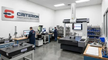
That combination — certifications, traceable metrology, and ERP-tracked inspection at every stage — is what gives engineering teams the documentation chain they need when a component cannot fail in the field.
Frequently Asked Questions
What tolerances can jig bore machining realistically achieve?
Standard jig bore work holds hole location to approximately ±.0005". Ultra-precision work on purpose-built machines with thermal control reaches 1–2 microns (±.0001" or better). Achievable tolerance depends on machine condition, thermal environment, part material, and bore geometry—particularly the length-to-diameter ratio of the feature.
What is the difference between jig boring and CNC boring on a machining center?
Jig boring machines are purpose-built for extreme positional accuracy—precision linear scales, low-runout spindles, and rigid guideways designed around dimensional stability—while CNC machining centers are general-purpose platforms optimized for throughput and versatility. Jig boring achieves tighter location tolerances and better geometric consistency, typically at lower throughput.
When should jig boring be specified instead of reaming or standard boring?
Specify jig boring when hole location must be corrected (not just diameter refined), when multiple holes require precise relative positioning, or when diameter and geometric tolerances exceed what drilling and reaming can reliably achieve. Reaming cannot correct position—it only improves diameter and finish within an existing hole.
What materials are suitable for tight tolerance jig bore machining?
Jig boring works across virtually any machinable metal—aluminum, stainless steel, titanium, tool steel, and specialty alloys including Inconel 718. Titanium and nickel-based alloys require parameter adjustments for thermal expansion and work hardening, but tight tolerances remain achievable with proper process control.
How is a tight tolerance jig-bored hole inspected and verified?
CMM measurement provides full geometric characterization—diameter, roundness, cylindricity, and true position in a single setup. Air gauging delivers fast, accurate diameter checks for production verification. Both require thermal stabilization of the part at 20°C (68°F) before final measurement is recorded to prevent thermal expansion from introducing false readings.
What industries most commonly require tight tolerance jig bore machining?
Aerospace, defense, medical device, and photonics/optics are the primary industries. Alignment-critical structural bores, bearing fits, actuator housings, optical component housings, and surgical instrument features all share one characteristic: bore location errors measured in ten-thousandths of an inch are enough to cause failure.