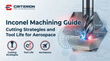
Introduction
Inconel superalloys form the backbone of modern aerospace engineering—powering jet engines, turbine assemblies, and exhaust systems at temperatures exceeding 1,200°F where conventional alloys fail. Yet this exceptional performance comes at a steep manufacturing cost: Inconel 718 scores just 12% on the AISI Machinability Index, making it one of the most difficult materials to machine reliably.
For aerospace manufacturers, a single work-hardened surface or premature tool failure can compromise component integrity—threatening flight safety and triggering costly production delays. The stakes leave no margin for error.
The challenges are real: rapid work hardening that can exceed tool hardness, extreme heat concentration at cutting edges, and tool life measured in minutes rather than hours.
This guide covers what aerospace machinists need to navigate Inconel successfully:
- Optimal cutting parameters for Inconel 718 and 625
- Tool selection and coating technologies that extend tool life
- Fixturing and coolant strategies for aerospace-grade surface finishes
- Criteria for selecting certified machining partners capable of meeting AS9100 requirements
TLDR: Key Takeaways for Aerospace Inconel Machining
- Carbide tools with TiAlN or AlTiN coatings are essential; plan for tool replacement after just 20-40 minutes of cutting time
- Maintain cutting speeds of 60-100 SFM with feeds of 0.001-0.003 in/tooth to prevent catastrophic work hardening
- High-pressure coolant systems (500+ PSI) handle chip evacuation and heat concentration — both failure points in Inconel operations
- Continuous cutting without interruption prevents work-hardening; each peck cycle makes subsequent cuts exponentially harder
- Qualified machining partners need aerospace-specific process experience, CMM dimensional verification, and ITAR registration — not just general precision shop credentials
Understanding Inconel Alloys for Aerospace Applications
What Makes Inconel Essential for Aerospace
Inconel holds its strength above 1200°F — the threshold where aluminum melts and titanium begins to oxidize. This heat resistance, combined with exceptional oxidation resistance and fatigue strength, makes it indispensable for aerospace applications operating in extreme thermal environments.
The alloy retains strength up to 700°C (1292°F) in turbine discs spinning at thousands of RPM, resists hot corrosion in exhaust gas streams, and holds dimensional stability under cyclic thermal loading.
In flight-critical systems, that stability is non-negotiable. Material degradation at operating temperatures can lead to engine failure, structural collapse, or loss of aircraft.
Typical aerospace applications include:
- Turbine blades and discs in jet engines
- Combustion chambers and afterburner components
- Exhaust systems and thrust reversers
- High-temperature fasteners and structural fittings
- Rocket engine components for space applications
Common Aerospace Inconel Grades
Inconel 718 dominates aerospace applications due to its age-hardenable microstructure that delivers exceptional strength. It maintains tensile strength above 180 ksi at elevated temperatures and offers excellent creep resistance up to 1300°F. This makes it ideal for turbine discs, structural engine components, and fasteners subjected to high stress and thermal cycling.
Inconel 625 offers superior corrosion resistance and is easier to weld than 718, though with slightly lower strength. It excels in temperatures up to 980°C (1796°F) and resists oxidation and hot corrosion better than 718. Aerospace applications include exhaust systems, ducting, combustion transition liners, and components exposed to corrosive exhaust gases.
Comparison: Inconel 718 vs. 625
| Property | Inconel 718 | Inconel 625 | Machining Impact |
|---|---|---|---|
| Machinability Rating | 12% | 17% | 625 machines slightly easier but still requires specialized approach |
| Max Service Temp | 700°C (1292°F) | 980°C (1796°F) | 625 suited for hottest sections; 718 for high-stress rotating parts |
| Strengthening | Precipitation hardened | Solid solution | 718 more prone to work hardening during cutting |
| Typical Cutting Speed | 60-100 SFM | 60-100 SFM | Both require conservative speeds; 625 tolerates slightly higher feeds |
Why Inconel Is Difficult to Machine
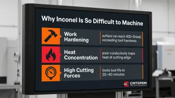
The 12% machinability rating of Inconel 718 reflects three compounding challenges that destroy conventional machining approaches:
- Work hardening under the cut: Inconel's austenitic structure hardens as the tool deforms it — sometimes reaching 400+ Brinell hardness in the affected zone. That layer can exceed the hardness of the cutting tool itself, compounding wear on every subsequent pass.
- Heat concentration at the cutting edge: Inconel conducts heat poorly, so thermal energy stays at the tool tip rather than dissipating into the workpiece. Cryogenic cooling with liquid nitrogen reduces cutting temperatures by nearly 12% — a significant margin that illustrates how extreme the heat buildup gets.
- High cutting forces throughout the operation: The alloy's strength stresses machine tools, causes deflection in thin-walled sections, and accelerates wear through combined mechanical and thermal loading. These forces, stacked on top of heat and work hardening, limit tool life to 20-40 minutes of actual cutting time.
Aerospace Quality and Tolerance Requirements
Aerospace Inconel components routinely require tight tolerances and controlled surface finishes:
- Dimensional tolerances: ±0.0002" or tighter on critical features
- Functional surface finish: 32 Ra or better
- Sealing surfaces: 16-32 Ra
These specifications directly govern fatigue life, sealing effectiveness, and dimensional stability under thermal cycling — not just dimensional accuracy for its own sake.
Surface integrity matters as much as dimensional accuracy. Machining-induced defects — micro-cracks, recast layers, residual tensile stresses — can initiate fatigue failures in service.
White layers from aggressive machining can reach 2.2 times the hardness of the base material, creating brittle zones that crack under cyclic loading.
AS9100 certification is the baseline quality management standard for aerospace machining suppliers, mandating documented process control, full traceability, and risk management. NADCAP accreditation for special processes (heat treating, NDT, chemical processing) is often required by OEMs for complete component manufacturing chains.
Essential Cutting Strategies for Inconel Machining
Continuous Cutting vs. Interrupted Cutting
The cardinal rule of Inconel machining: maintain continuous, uninterrupted cuts whenever possible. Each time a tool exits the material and re-enters, the previously cut surface work-hardens, creating a layer harder than the tool substrate. This forces the tool to cut through hardened material on re-entry, dramatically accelerating wear and increasing the risk of catastrophic tool failure.
Climb milling offers significant advantages over conventional milling. The chip forms at maximum thickness and tapers as the tool exits, directing heat into the chip rather than the workpiece. This reduces work hardening risk, improves surface finish, and extends tool life by 20-30% in typical applications.
When interrupted cutting is unavoidable:
- Use the sharpest possible tools to slice cleanly rather than deform material
- Ensure adequate coolant reaches the cutting zone before re-entry
- Follow through immediately without dwelling
- Plan toolpaths to minimize the number of interruptions
High-Efficiency Toolpath Strategies
Dynamic milling (also called adaptive clearing) transforms Inconel roughing economics. Instead of taking full-width cuts at shallow depths, this strategy uses light radial engagement (10-20% of tool diameter) with deeper axial engagement, maintaining constant chip load throughout the cut.
Benefits include:
- Wear distributed across the entire cutting edge rather than concentrated at one point
- Tool life extensions of 30-50% compared to conventional toolpaths
- Reduced heat concentration and work hardening
- Higher material removal rates despite conservative radial engagement
CAM software strategies that improve results:
- Gentle entry/exit ramps that avoid plunging directly into material
- Trochoidal (circular interpolation) milling for slots and pockets
- Avoiding sharp direction changes that shock the tool and cause chipping
- Maintaining constant engagement angle throughout the cut
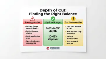
Depth of Cut and Stepover Considerations
For roughing operations, depth of cut should be 0.02-0.05 inches per pass with stepover of 10-15% of tool diameter. These parameters balance productivity against tool life and work hardening risk.
| Parameter Setting | What Happens |
|---|---|
| Too aggressive | Cutting forces exceed machine rigidity, causing deflection and chatter. Heat accelerates wear, and work hardening compounds with each pass. |
| Too conservative | The tool rubs rather than cuts, generating heat without proper chip formation. Surface work-hardens without efficient material removal. |
Adjust parameters based on:
- Part rigidity (reduce depth of cut for thin-walled sections)
- Machine capability (older or lighter machines require more conservative parameters)
- Tool condition (reduce feeds as tools approach end of life)
Drilling Strategies for Inconel
Use 118-degree drill point geometry without web thinning for holes in Inconel. Cobalt high-speed steel drills outperform solid carbide for holes under 0.5" diameter due to their toughness and resistance to chipping.
Coolant-through tooling is mandatory at minimum 500 PSI pressure. High-pressure coolant evacuates chips and prevents work hardening inside the hole, where chip evacuation problems cause rapid tool failure.
If peck drilling is unavoidable:
- Use minimal peck depth (0.1-0.2× hole diameter)
- Ensure complete chip evacuation between pecks
- Increase coolant pressure to maximum available
- Accept shorter tool life and plan accordingly
Spot drills are preferred over center drills to establish hole location. Their geometry is less prone to breakage and provides better guidance for the drill without creating a work-hardened starting surface.
Threading and Finishing Operations
Thread milling offers decisive advantages over tapping in Inconel. A single thread mill can produce 3-8 passes per hole at 60 SFM, and if the tool breaks mid-operation, you can replace it and continue without scrapping the part. Most shops see 15-25 holes per thread mill before replacement — a predictable, plannable interval.
Tapping should be the last resort—often you'll get one tap per hole due to rapid wear. If tapping is unavoidable:
- Use rigid tapping capability (not tension-compression holders)
- Apply sulfur-based cutting oil for extreme pressure lubrication
- Reduce speed to 50-70% of standard recommendations
- Plan for frequent tap replacement
Finish milling requires light radial engagement (5-10% of tool diameter) with multiple finish passes. Higher feed rates maintain chip formation and prevent rubbing, which degrades surface finish and accelerates tool wear.
Tool Selection and Tool Life Optimization
Cutting Tool Material Selection
Carbide tools are the practical standard for Inconel machining. Solid carbide end mills or carbide inserts with high cobalt content (8–12%) provide the toughness needed to resist chipping under interrupted cuts while maintaining hot hardness. Coated carbides achieve tool life of approximately 60 minutes under optimized conditions — roughly double that of uncoated tools.
Ceramic tools excel in high-speed continuous finishing cuts where superior hot hardness and oxidation resistance matter most. SiAlON ceramics can operate at speeds of 250–900 m/min (820–2950 SFM) for roughing, significantly increasing material removal rates. They're brittle, though, and require stable setups with minimal vibration.
For high-volume production or applications demanding maximum tool life, CBN (cubic boron nitride) tools allow cutting speeds 2–4 times higher than carbide. The cost premium is real, so CBN makes sense only when cycle volume justifies the investment.
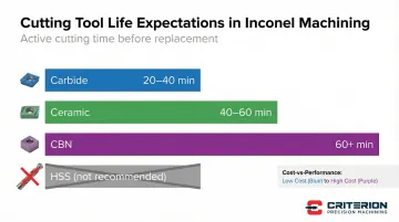
Tool life expectations by material:
- Carbide: 20–40 minutes under active cutting
- Ceramic: 40–60 minutes in ideal conditions with stable setup
- CBN: 60+ minutes but at significant cost premium
- HSS: Not recommended — wears too rapidly to be economical in Inconel
Tool Geometry and Design Features
Positive rake angles (5–15 degrees) reduce cutting forces and heat generation by making chip formation easier. The tool slices rather than pushes material, reducing the tendency for work hardening and built-up edge formation.
Edge geometry matters just as much as rake angle. Inconel requires sharp cutting edges — not honed or chamfered — to slice cleanly rather than deform the material. Edge radii above 15 µm increase cutting forces and degrade surface finish, so resist the instinct to add edge prep.
In deep cuts or long-overhang situations, variable helix and unequal spacing are worth specifying. These features break up the cutting frequency, preventing the resonance that destroys surface finish and accelerates tool failure.
For corner radius, 0.015–0.030" covers most aerospace applications. Smaller radii produce better finish but are more fragile; larger radii are stronger but leave visible tool marks.
Advanced Tool Coatings
TiAlN (Titanium Aluminum Nitride) is the industry standard for Inconel machining. It provides oxidation resistance up to 800°C and maintains hardness at elevated temperatures, extending tool life 20–30% compared to uncoated tools. TiAlN coatings with hardness of approximately 33 GPa resist abrasive wear while providing thermal protection.
AlTiN (Aluminum Titanium Nitride) features higher aluminum content for better heat resistance at higher cutting speeds. It forms a protective aluminum oxide layer at elevated temperatures, making it the better choice for high-speed milling where heat generation is severe.
Silicon-enhanced coatings represent the newest generation, showing 30–50% tool life improvements in Inconel applications. These coatings reduce friction and material adhesion, minimizing built-up edge formation.
Match coating to operation:
- AlTiN for milling operations at higher speeds
- TiAlN for drilling, turning, and general-purpose applications
- Uncoated tools wear too quickly to be economical in Inconel
Tool Life Management and Economics
Track time under load, not total cycle time. Inspect tools at 15–20 minute intervals for flank wear, checking for:
- Flank wear land exceeding 0.015"
- Notching at depth of cut line
- Built-up edge formation
- Chipping or micro-fractures
Getting this balance right has real consequences. Change tools too early and you're discarding usable life; run them too long and you risk work-hardening the part, dimensional errors, or a catastrophic failure that scraps the workpiece entirely.
For turning operations, use indexable inserts and rotate or flip them at scheduled intervals. This maintains consistency and prevents the gradual degradation that comes from running inserts to complete failure.
Cost calculation framework:
Tool cost per part = (Tool cost + Resharpening cost) ÷ Number of parts per tool
Factor this into part pricing alongside cycle time. A $50 carbide end mill that yields 8 parts adds $6.25 per part in tool cost — worth knowing before quoting a tight-margin aerospace job.
Maintain detailed tool life logs by operation, material batch, and machine. Inconel hardness can vary noticeably between heats, and those variations will show up in your tool wear data before they show up in your scrap rate.
Cutting Parameters and Process Control for Inconel
Cutting Speed and Feed Rate Guidelines
Conservative cutting speeds are non-negotiable for Inconel. For carbide tools, maintain speeds of 60-100 SFM for milling and 35-45 m/min (115-148 SFM) for turning. Ceramic tools can operate at higher speeds—up to 150 SFM or more—but only in stable, rigid setups.
Feed rates must maintain adequate chip thickness to cut rather than rub:
- Finishing operations: 0.001-0.003 inches per tooth
- Roughing operations: 0.003-0.006 inches per tooth
- Maintain chip thickness of 0.001-0.003" regardless of operation
Lower speeds reduce heat, but feed rate must stay high enough to form proper chips. If feed rate drops too low relative to cutting speed, the tool rubs rather than cuts — work-hardening the surface and stalling material removal.
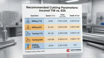
Recommended Parameters: Inconel 718 vs. 625
| Operation | Material | Tool | Speed (SFM) | Feed (in/tooth) | Depth of Cut |
|---|---|---|---|---|---|
| Milling | 718 | Carbide | 60-100 | 0.001-0.003 (finish) | 0.02-0.05" |
| Milling | 625 | Carbide | 80-120 | 0.002-0.004 (finish) | 0.02-0.05" |
| Turning | 718 | Carbide | 110-150 | 0.003-0.006 | 0.030-0.080" |
| Turning | 625 | Carbide | 150-200 | 0.004-0.007 | 0.030-0.080" |
| Drilling | 718/625 | Cobalt HSS | 40-60 | 0.001-0.002 | Full diameter |
Coolant and Lubrication Strategies
High-pressure coolant at 500-1000+ PSI is essential for Inconel machining. Minimum pressure of 70 bar (approximately 1000 PSI) breaks through the vapor barrier at the cutting edge, delivering coolant where it's needed most.
Coolant type selection:
- Water-soluble synthetics: General-purpose milling and turning, good heat removal
- Sulfur-based cutting oils: Threading, tapping, and operations requiring extreme pressure lubrication
- MQL (minimum quantity lubrication): Specific finishing operations where flood coolant interferes with chip evacuation
Cryogenic cooling with liquid nitrogen delivers the most aggressive thermal control available. Research shows LN2 cooling reduces cutting temperatures by 11.98% compared to dry cutting and can improve tool life by 40-60%. The specialized equipment cost is offset quickly in high-volume aerospace production, where tool life and surface integrity directly affect program economics.
Proper coolant application technique:
- Aim directly at the cutting edge, not the general area
- Use through-tool delivery whenever possible
- Maintain flow rate of 1-2 gallons per minute minimum
- Position nozzles to follow the tool through the cut
Rigidity and Fixturing Requirements
Inconel's high cutting forces demand maximum rigidity throughout the system. Any deflection—in the machine, tool holder, or workpiece fixturing—causes dimensional inaccuracy, chatter, and accelerated tool wear.
Fixturing best practices:
- Use shortest tool overhang possible (3× diameter maximum, 2× preferred)
- Heavy-duty vises or custom fixtures for all operations
- Support thin-walled parts with backup plates or temporary wax filling
- Multiple contact points to distribute clamping forces
Machine requirements:
- Rigid CNC mills with 40-taper or larger spindles (CAT50/HSK100 preferred for heavy roughing)
- Turning centers with minimum 20 HP for adequate torque at low RPM
- Spindle runout under 0.0002" to prevent premature tool wear
- High-torque capability at low speeds (Inconel requires torque, not RPM)
Any compromise in rigidity compounds through the process. A slightly flexible fixture allows workpiece movement, which increases cutting forces, which drives further deflection and faster tool wear. Each failure mode feeds the next, and the result is scrapped parts and shortened tool life.
Common Machining Challenges and Solutions for Inconel
Work Hardening Prevention and Recovery
Work hardening occurs when plastic deformation ahead of the cutting edge creates a hardened layer that can reach 400+ Brinell hardness—harder than the carbide substrate of cutting tools. Once established, this layer makes subsequent cuts nearly impossible and forces tool replacement or process changes.
Prevention strategies:
- Use sharp tools that slice cleanly rather than deform material
- Maintain adequate feed rates to cut rather than rub (minimum 0.001" chip thickness)
- Employ continuous cutting without interruption or dwelling
- Start with solution-annealed (softened) material when specifications allow
Recovery options:
- Switch to ceramic tools or CBN that can cut the hardened layer
- Use EDM to remove the hardened surface layer without mechanical forces
- Anneal the part if geometry and specifications allow
- Increase cutting forces with more rigid setup and fresh sharp tools
Prevention is always the better path. Once a hardened layer forms on an aerospace component, re-work options are limited — annealing may affect heat treatment, and aggressive re-cutting risks dimensional loss on already tight-tolerance features.
Built-Up Edge and Galling
Work hardening attacks the workpiece. Built-up edge (BUE) attacks the tool. At low cutting speeds, Inconel adheres directly to the cutting edge, changing effective tool geometry and eventually fracturing away — taking carbide with it. The result is torn surface finish and unpredictable tool life.
To prevent BUE:
- Maintain minimum cutting speed of 60 SFM to plasticize chips
- Use coated tools (TiAlN/AlTiN) to reduce chemical adhesion
- Ensure adequate coolant reaches the cutting edge
- Replace tools immediately when BUE appears—it only gets worse
Galling is especially problematic in drilling and threading operations where chip evacuation is difficult and speeds are lower. Use appropriate sulfur-based lubricants for these operations and avoid dwelling or slow feed rates that promote material adhesion.
Tool Breakage and Chipping
Common causes:
- Excessive feed rate for worn tools that can no longer handle the load
- Interrupted cuts without proper entry/exit strategy
- Inadequate fixturing allowing workpiece movement
- Using tools beyond their life expectancy
Troubleshooting steps:
- If tools break consistently, reduce feed rate by 20-30%
- Verify setup rigidity—check for workpiece movement or tool holder issues
- Check for spindle runout or tool holder taper contamination
- Ensure coolant is reaching the cutting zone
- Inspect tools more frequently and replace before catastrophic failure
Implement a tool life tracking system that replaces tools at 80% of expected life. Log spindle hours, material lot, and cutting parameters for each tool — that data quickly reveals which variables drive premature failure and where your intervals need tightening.
Quality and Inspection Requirements for Aerospace Inconel
Surface Finish and Integrity
Typical aerospace surface finish requirements vary by application:
- 32–63 Ra: Functional surfaces, general aerospace components
- 16–32 Ra: Sealing surfaces, mating features
- 8 Ra or better: Critical dynamic surfaces, some turbine components
Surface integrity concerns extend beyond roughness measurements. Key issues to monitor include:
- Heat-affected zones: Visible discoloration signals temperatures high enough to alter material properties and compromise fatigue life
- Residual tensile stress: Stress in the surface layer promotes crack initiation under cyclic loading
- Micro-cracks: Caused by excessive heat or dull tools; often invisible without magnification
Each of these failure modes has a corresponding inspection method to catch problems before a part reaches assembly:
- Visual inspection for burns, discoloration, or obvious defects
- Profilometer (stylus or optical) for surface roughness verification
- Dye penetrant or fluorescent penetrant inspection for crack detection on critical components
- Metallographic cross-sectioning to evaluate subsurface damage, grain deformation, and heat-affected zone depth